
Injector for plasma mass filter

Inactive Publication Date: 2005-08-11
ARCHIMEDES OPERATING
View PDF11 Cites 10 Cited by
  • Summary
  • Abstract
  • Description
  • Claims
  • Application Information

AI Technical Summary

Benefits of technology

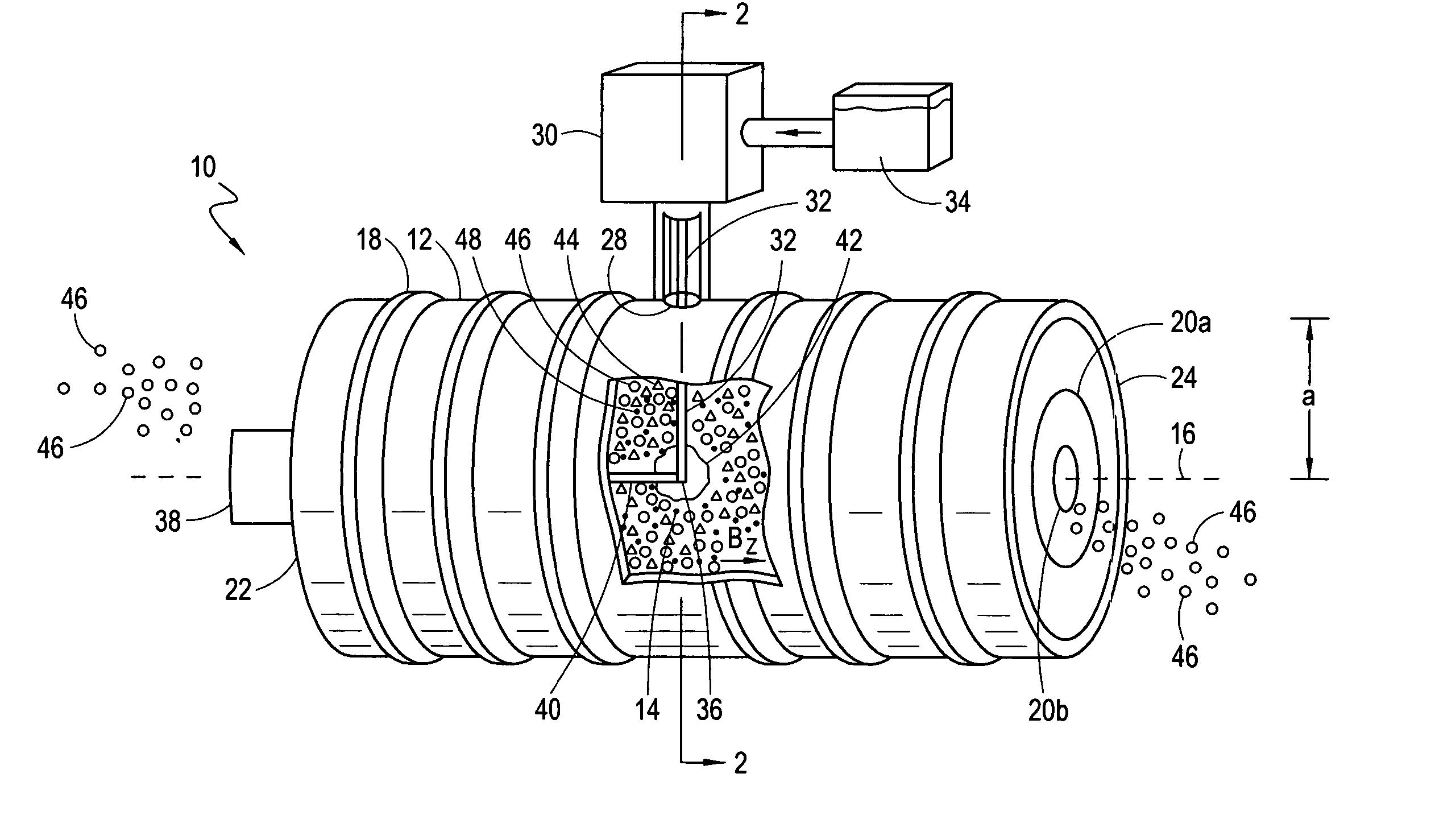
[0014] It is intended for the present invention that the injector be configured to produce a fluid jet having a predetermined velocity and radius. In accordance with the mathematics outlined above, the velocity and radius of the fluid jet are selected and controlled to create a fluid jet that can pass through the rotating plasma with minimal evaporation of the feed material during transit through the rotating plasma. This allows most of the vaporization to occur at the target volume rather than near the wall of the filter where evaporation would result in a loss of feed material from the plasma. Additionally, the velocity and radius of the fluid droplets are selected and controlled to minimize deflection of the feed material by the rotating plasma. By minimizing the deflection of the droplets in this manner, the droplets can consistently reach the target volume, regardless of fluctuations in the rotational speed and density of the plasma. It is to be appreciated that several factors will influence the selection of the velocity and radius of the fluid jet droplets to minimize transit vaporization and deflection. These include the characteristics of the feed material, the density and rotational speed of the plasma, and the size of the plasma chamber.

Problems solved by technology

This allows most of the vaporization to occur at the target volume rather than near the wall of the filter where evaporation would result in a loss of feed material from the plasma.

Method used


Image

  • Injector for plasma mass filter
  • Injector for plasma mass filter
  • Injector for plasma mass filter

Examples


Embodiment Construction

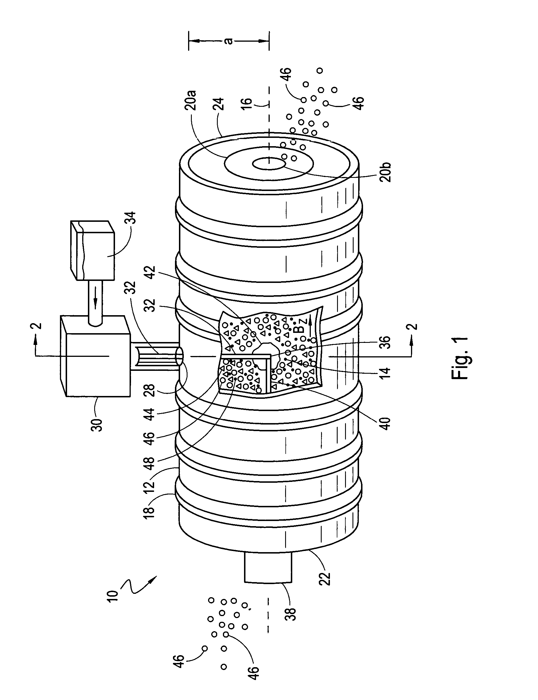
[0022] Referring to FIG. 1, a tandem plasma mass filter having an injector system in accordance with the present invention is shown and generally designated 10. As shown, the filter 10 includes a substantially cylindrical shaped wall 12 which surrounds a chamber 14, and defines a longitudinal axis 16. The actual dimensions of the chamber 14 are somewhat, but not entirely, a matter of design choice. Importantly, the radial distance “a” between the longitudinal axis 16 and the wall 12 is a parameter which will affect the operation of the filter 10, and as clearly indicated elsewhere herein, must be taken into account.

[0023] It is also shown in FIG. 1 that the filter 10 includes a plurality of magnetic coils 18 which are mounted on the outer surface of the wall 12 to surround the chamber 14. In a manner well known in the pertinent art, the coils 18 can be activated to create a magnetic field in the chamber 14 which has a component Bz that is directed substantially parallel to the long...


PUM

PropertyMeasurementUnit
Diameteraaaaaaaaaa
Massaaaaaaaaaa
Magnetic fieldaaaaaaaaaa

Abstract

An injection system for introducing feed material into a plasma mass filter includes an injector for producing a jet of feed material. For a plasma mass filter having a cylindrical wall that surrounds a plasma chamber, the injector is mounted to the outside of wall and oriented to deliver a feed jet into the plasma chamber. Specifically, the injector is oriented to deliver a jet that is directed toward a target volume in the chamber that is located substantially on the longitudinal axis defined by the cylindrical wall. More specifically, the feed material is injected into the chamber to the target volume along a path that is transverse to the direction of plasma rotation in the chamber. A vaporization energy source can be included to generate and direct an energy beam toward the target volume to vaporize the jet of feed material as the jet arrives at the target volume.

Description

FIELD OF THE INVENTION [0001] The present invention pertains generally to systems and methods for introducing a feed material into a plasma and thereafter converting the feed material into plasma by evaporating and ionizing the feed material. More particularly, the present invention pertains to systems for radially injecting a feed material into a rotating plasma for subsequent conversion of the feed material to plasma. The present invention is particularly, but not exclusively, useful for continuously injecting a multi-constituent feed material into a plasma mass filter to allow for the subsequent separation of the feed material into its constituents. BACKGROUND OF THE INVENTION [0002] A fundamental step in any plasma processing operation is the conversion of a feed material into a plasma. For plasma separation processes wherein charged particles in the plasma are to be separated according to their respective mass to charge ratios, it is generally desirable to continuously introduc...

Claims


Application Information

Patent Timeline
IPC IPC(8): B01D17/06
CPCH05H1/42B01D17/06
Inventor OHKAWA, TIHIRO
Owner ARCHIMEDES OPERATING
Learn More