Rapid deployment flood control system

a flood control and rapid technology, applied in the field of rapid deployment flood control system, can solve the problems of large amount of land, high cost of engineering and construction, and destruction of valuable historic and ecologic treasures

Inactive Publication Date: 2005-08-04
YOUNG CLIFFORD RAY
View PDF0 Cites 14 Cited by
  • Summary
  • Abstract
  • Description
  • Claims
  • Application Information

AI Technical Summary

Benefits of technology

[0021] In a more specific aspect, the flood control method includes the steps of: (a) identifying a flood zone area prior to flooding, the flood zone area being proximate a body of water having a top surface, the body of water being susceptible to flooding whereby the top surface of the body of water rises and the water flows into, and onto, the flood zone area; (b) identifying a flood protection barrier area proximate the flood zone area; (c) providing a substantially level support surface within the flood protection barrier area; (d) providing a plurality of containers, the containers having a bottom panel, a pa...

Problems solved by technology

Some of the disadvantages with stationary flood control systems are the amount of time needed and the high cost to engineer and build them.
Other disadvantages are that these systems consume a tremendous amount of land and result in the destruction in valuable historic and ecologic treasures.
Other disadvantages are that the dam is fixed in a permanent location and the designed capacity that may be inadequate because the amount of rain can vary greatly.
Also the adverse impact upon the environment that these systems produce is now widely recognized.
In some areas dams are being destroyed.
Yet this does not negate the fact that a viable means, for flood control is needed in place of these systems hence this device will meet this need.
Sandbags, however, have a number of logistical problems and disadvantages.
One of the problems with sandbags lies in the amount of human labor required for their installation Each bag must be filled, usually by hand, and then placed at the location where the barrier is being constructed.
Another problem is obtaining and transporting sufficient quantities of sand for filling purposes, which is often very expensive and time-consuming.
Another problem is the logistics of coordinating the human effect of filling the bags and placing them at the right location within the appropriate time frame.
Another problem that can make the use of sandbags very difficult is the fact that sandbags must often be placed in pouring rain creating safety hazards.
Still another problem is that the placement of the ba...

Method used


Image

  • Rapid deployment flood control system
  • Rapid deployment flood control system
  • Rapid deployment flood control system

Examples


Embodiment Construction

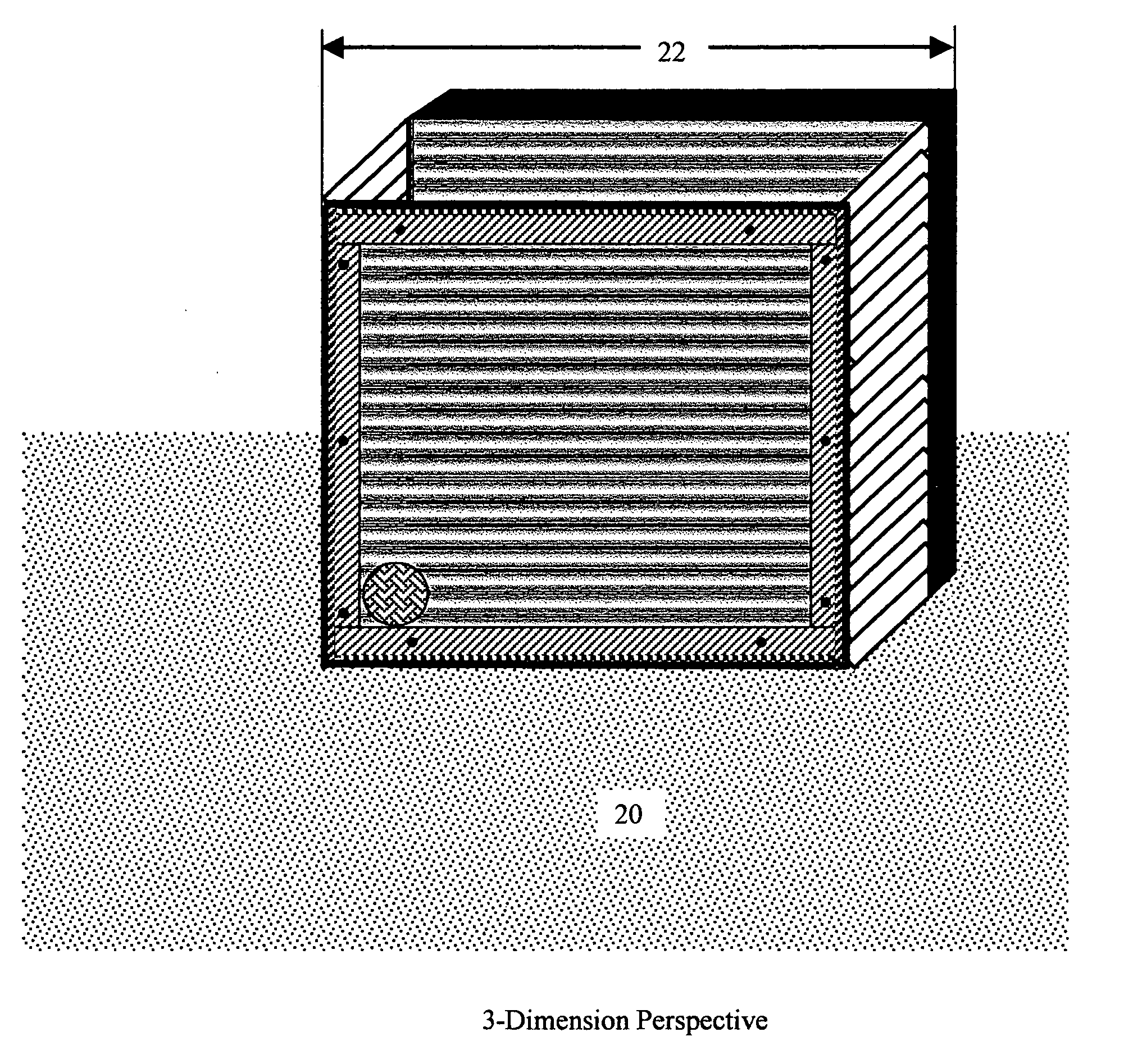
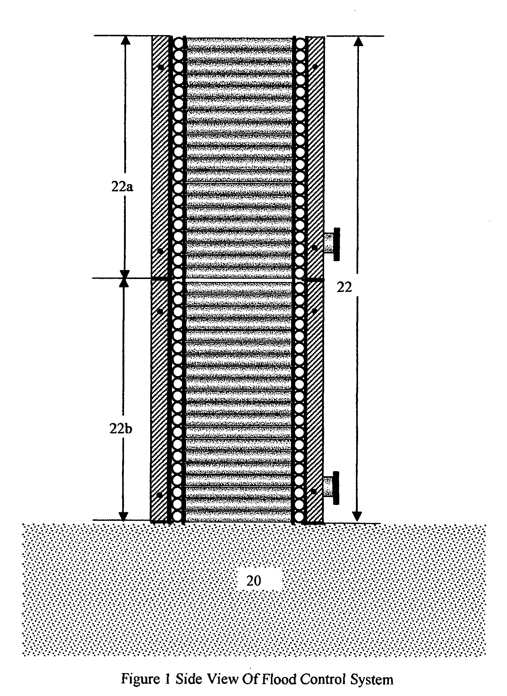
[0044] As mentioned above, the invention is preferably directed to flood control systems. Both methods and apparatus for flood control are within the scope of the invention. We wil now describe specific embodiments, examples and versions of the invention, for the purpose of enabling others skilled in the art to make and use our invention. It is understood, however, that the invention is not limited to these specific embodiments, examples and versions. Nor is the invention restricted to flood control as such, but may be used in other applications involving the forming of a barrier to prevent or restrict the flow of any liquid.

[0045] A person skilled in the art that has read this patent or seen the invention being used, described, or implemented will recognize many variations of the invention that might not be expressed here. Thus, it is the claims below that should be referred to for purposes of determining the scope of the invention, not only the literal elements therein, but also ...


PUM


Abstract

A flood control system involving a means of providing a plurality of lightweight, mobile but strong containers having a rigid bottom portion, rigid end panels and rigid sidewalls operably connecting the bottom portion and end panels. The system provides means of attaching the containers to one another. The system provides for a plurality of containers to be freely positioned at selected locations proximate to a rising water level in an abutting relationship to form a barrier. The system provides means for the containers to be self-filled with rising floodwater due to the increase pressure from the rise in the water level.

Description

[0001]Current U.S.205 / 114; 220 / 1.6; 220 / 495.06; 220 / 646; 450 / 20;Class:405 / 111Intern'l Class:E02B 003 / 12Field Of405 / 20, 70, 71, 121, 108-111, 114-115, 110, 16, 17 107,Search:220 / 1.6, 495.05, 495.06, 62.11, 608, 623, 669-673,62.18, 645, 646REFERENCE CITED [0002]U.S. Patent Documents422901March, 1890Arnett405 / 114848319March, 1907Phillips220 / 621077791November, 1913Blaauw3191386June, 1965Wiegel et al3213628October, 1965Serota3901406August, 1975Kivett220 / 84362433December, 1982Wagner et al4370075January, 1983Scales405 / 204692060September, 1987Jackson, III4869617September, 1989Chiodo4921373May, 1990Coffey5040919August, 1991Hendrix5059065October, 1991Doolaege5125767June, 1992Doolaege5154302October, 1992Alcorn220 / 45183180February, 1993Hawkins et al220 / 6695188460February, 1993Dorse220 / 4955632573May, 1997Baker5645373July, 1997Jenkins5655679August, 1997Schutz220 / 15673664October, 1997Lassanske220 / 4955779391July, 1998Knight405 / 1145,993,113November, 1999Darling405 / 1146,012,872January, 2000Perry, et ...

Claims


Application Information

Patent Timeline
IPC IPC(8): E02B3/10
CPCE02B3/108
Inventor YOUNG, CLIFFORD RAY
Owner YOUNG CLIFFORD RAY
Why Eureka
Try Eureka