
Computed tomography system

a tomography and computed tomography technology, applied in the direction of material analysis using wave/particle radiation, instruments, applications, etc., can solve the problems of high installation cost, large real estate consumption of freestanding installations in airport terminals, and user extensive modification of existing passenger processing protocols

Active Publication Date: 2005-08-04
REVEAL IMAGING TECH +1
View PDF38 Cites 32 Cited by
  • Summary
  • Abstract
  • Description
  • Claims
  • Application Information

AI Technical Summary

Problems solved by technology

Freestanding installations consume a great deal of real estate in the airport terminal and require the user to make extensive modifications to existing passenger processing protocols.
Whether built into the conveyor just aft of the check-in desks or further down the baggage handling system, these installations are very expensive and require extensive modifications to the baggage conveyor system.

Method used


Image

  • Computed tomography system
  • Computed tomography system
  • Computed tomography system

Examples


Embodiment Construction

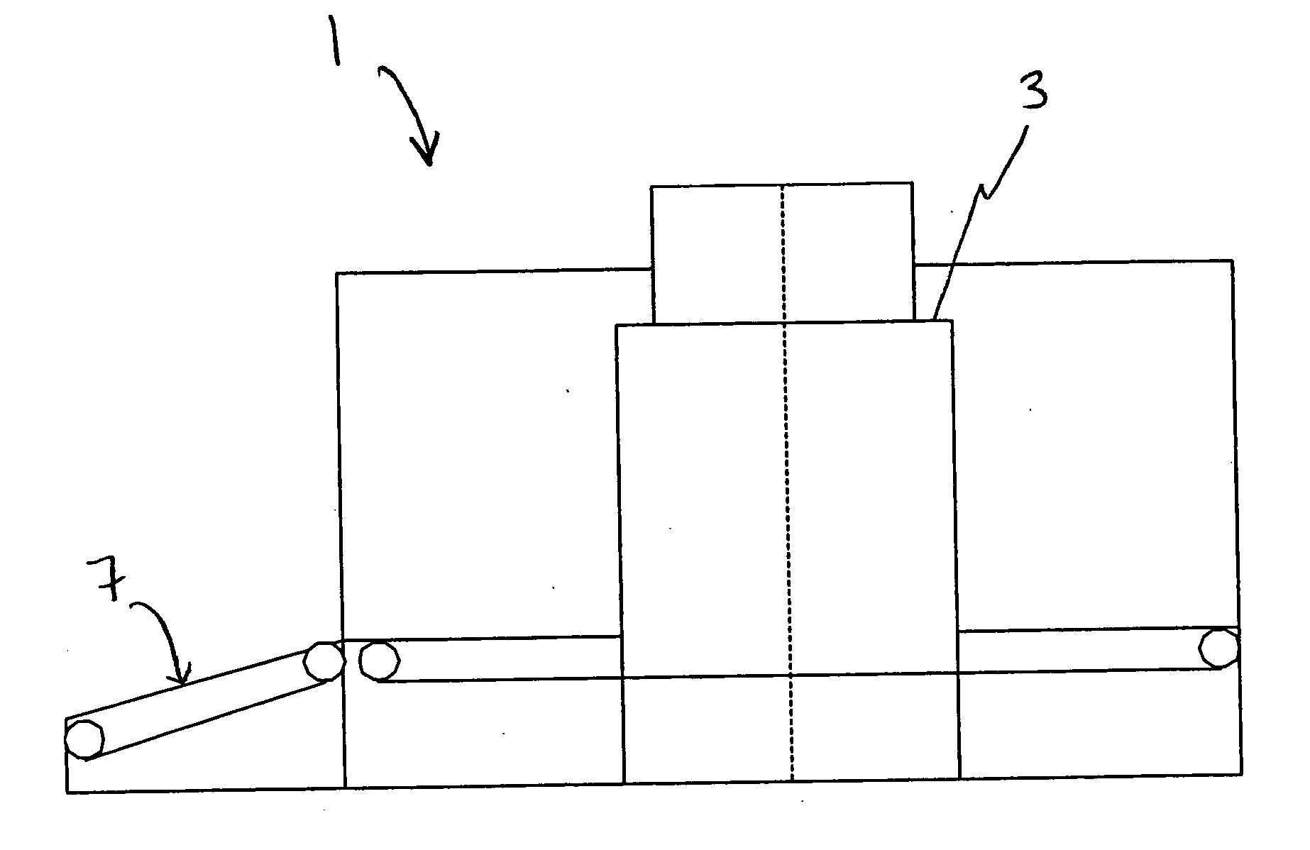
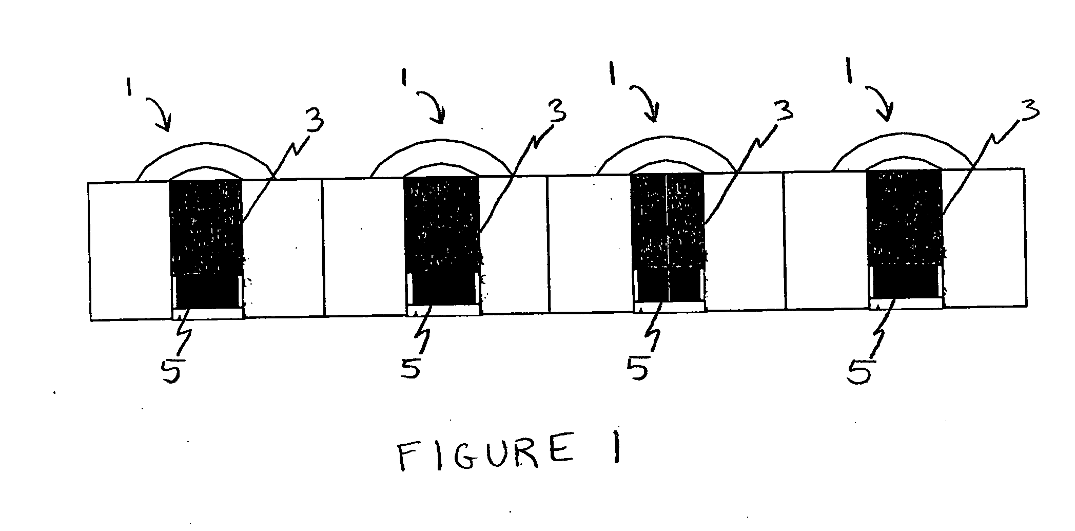
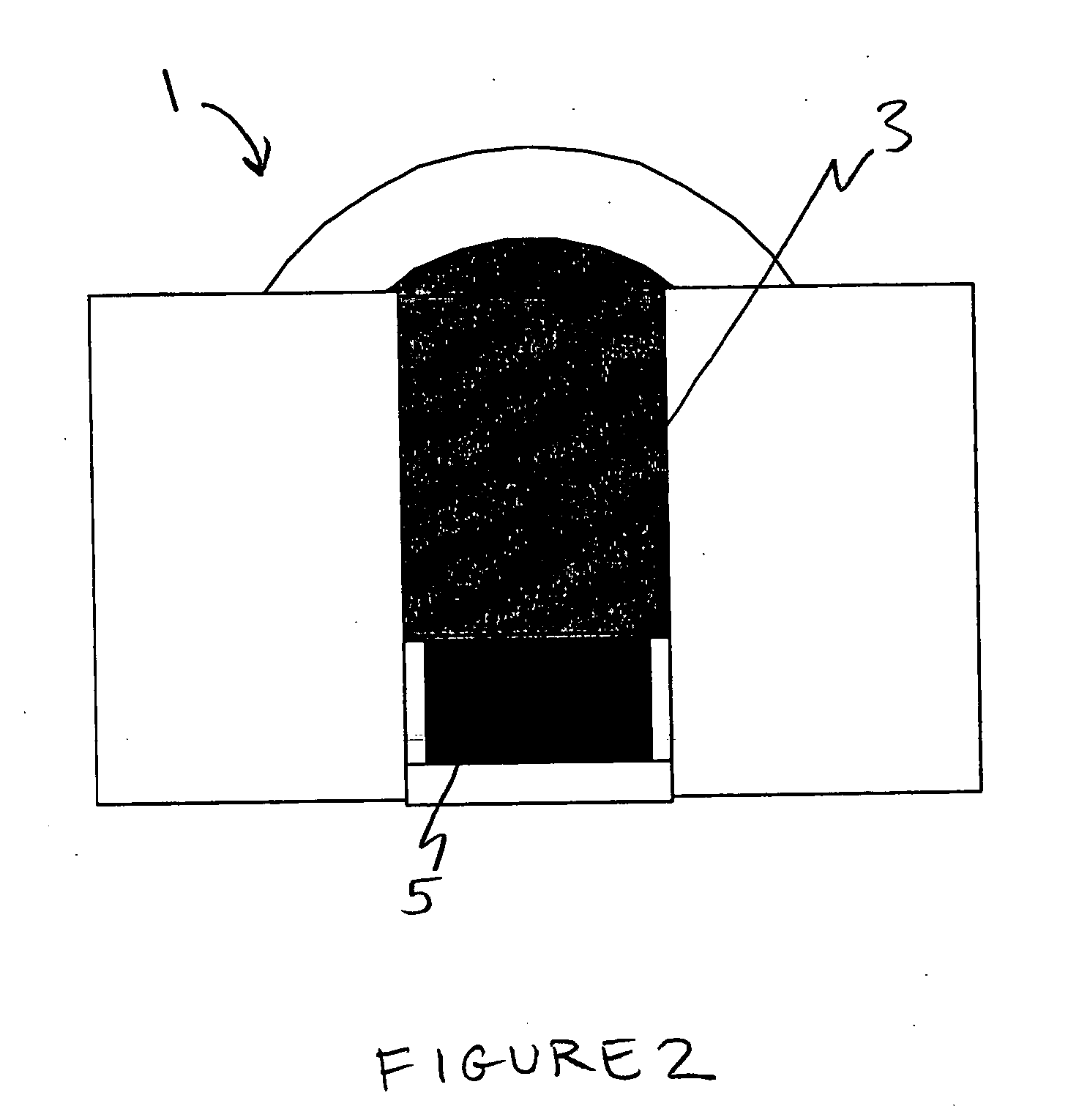
[0014] One embodiment of the invention is directed to a smaller and cheaper system than is provided by traditional detection systems, and which is designed to be integrated into a check-in desk. Installing the inspection system within the check-in desk addresses critical drawbacks associated with existing equipment.

[0015] Standard check-in time is consistent with the screening time needed by the CT system. Screening at the check-in desk keeps the passenger with his bag until the bag is cleared, thereby avoiding the need to re-unite the passenger and bag at another point. A check-in desk solution does not require the complete baggage handling system to track 100% of all bags, which would require most US airports to update their baggage handling systems (BHS) at significant expense.

[0016] The check-in desk system may replace the existing check-in desk. Space requirements may be 15-20% greater than the existing check-in counters. The check-in desk system may be both freestanding and ...


PUM

PropertyMeasurementUnit
beam angleaaaaaaaaaa
rotation angleaaaaaaaaaa

Abstract

An embodiment of the invention is directed to a computed tomography device, comprising a tunnel to receive baggage, an x-ray source providing an x-ray beam that intersects the tunnel and has a beam angle of 120°, a gantry that oscillates relative to the tunnel through an oscillation angle that equals 270°, and a plurality of detectors. The plurality of detectors are mounted to the gantry and adapted to receive x-rays from the x-ray source. In addition, the plurality of detectors are arranged in a horseshoe-shaped configuration in which at least one first detector is located a furthest distance from the x-ray source and at least one second detector is disposed on each side of the at least one first detector and is disposed closer to the x-ray source than the at least one first detector.

Description

FIELD OF THE INVENTION [0001] The present invention is directed to the field of computed tomography detection systems. BACKGROUND OF INVENTION [0002] On Nov. 16, 2001, the U.S. Congress passed the Aviation and Transportation Security Act. The Act required U.S. airlines to perform 100% checked baggage inspection starting Jan. 18, 2002 using any means available, with a requirement to inspect 100% of the checked bags using FAA Certified Explosives Detection Systems (EDS) by Dec. 31, 2002. Accordingly, a system that enables the airlines and airports to comply with those regulations while maintaining passenger and baggage flow through the terminal is needed. [0003] The currently available EDS technology can be deployed in the terminal in front of the check-in counter, creating a new passenger queue and significant logistical problems for the airlines, or they can be integrated into the baggage conveyor system behind the check-in counters. [0004] There are currently two deployment options...

Claims


Application Information

Patent Timeline
Patent Type & Authority Applications(United States)
IPC IPC(8): G01N23/04G01V5/00
CPCG01N23/046G01N2223/419G01V5/005G01V5/0041G01V5/224G01V5/226
Inventor ELLENBOGEN, MICHAEL P.
Owner REVEAL IMAGING TECH
Learn More