
Radiation image sensor and making method of same

a technology of image sensor and x-ray, applied in the direction of x/gamma/cosmic radiation measurement, instruments, radiation controlled devices, etc., can solve the problems of difficult to form a moisture barrier, x-rays cannot be refractioned, pan and zoom images with optical systems are not available, etc., to prevent peeling, improve the moisture resistance of scintillator, and improve the effect of moisture resistan

Active Publication Date: 2005-08-04
HAMAMATSU PHOTONICS KK
View PDF7 Cites 34 Cited by
  • Summary
  • Abstract
  • Description
  • Claims
  • Application Information

AI Technical Summary

Benefits of technology

The present invention provides a radiation image sensor with an improved structure for detecting mammary cancer early on. The sensor has a unique design that allows for accurate X-ray imaging up to the base part of the mammary gland with high resolution while securing moisture resistance for the scintillator. The sensor is fixed on a mount substrate with an adhesive and a pressure difference between the two surfaces of the substrate. A protective film is placed on the sensor to capture the X-ray image and is fixed on the mount substrate. The sensor is designed to have effective pixels up to the extreme end of the peripheral region. The scintillator is protected by the resin layer and the peripheral part of the protective film is fixed on the mount substrate. The sensor is fixed on the mount substrate with an adhesive and the adhesive is placed so as to surround the through holes in the mount substrate. The method of producing the sensor involves preparing the image sensor assembly and forming the protective film.

Problems solved by technology

Particularly, reflection, refraction, pan and zoom of image with an optical system are not available to X-rays, different from visible light.
This means that the scintillator and image pickup device have to be located in at least one peripheral region of the imaging sensor, but in this structure, it is difficult to form the moisture barrier as in the technology of Document 1.

Method used


Image

  • Radiation image sensor and making method of same
  • Radiation image sensor and making method of same
  • Radiation image sensor and making method of same

Examples


Embodiment Construction

[0028] The preferred embodiments of the present invention will be described below in detail with reference to the accompanying drawings. To facilitate the comprehension of the explanation, the same reference numerals denote the same parts, where possible, throughout the drawings, and a repeated explanation will be omitted.

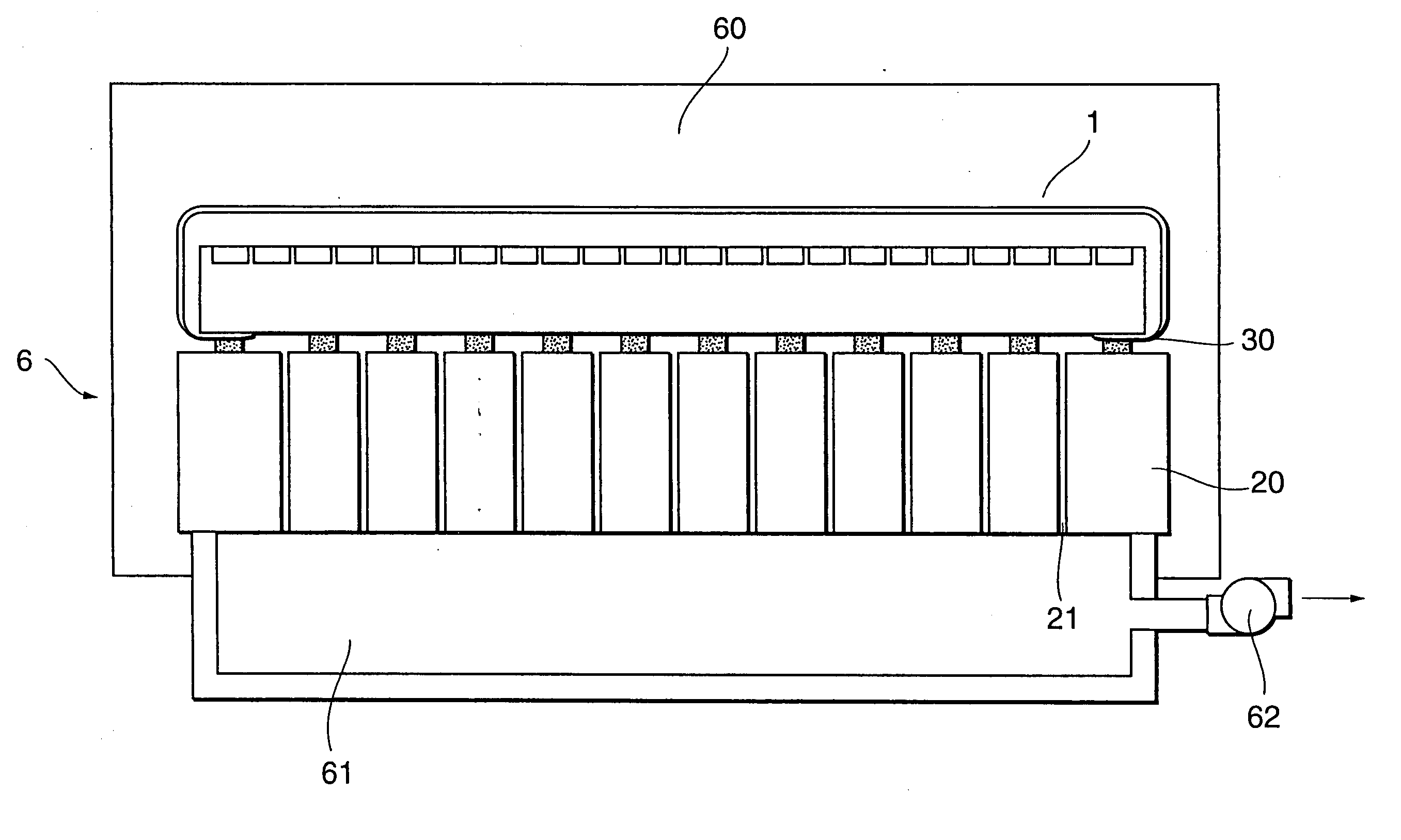
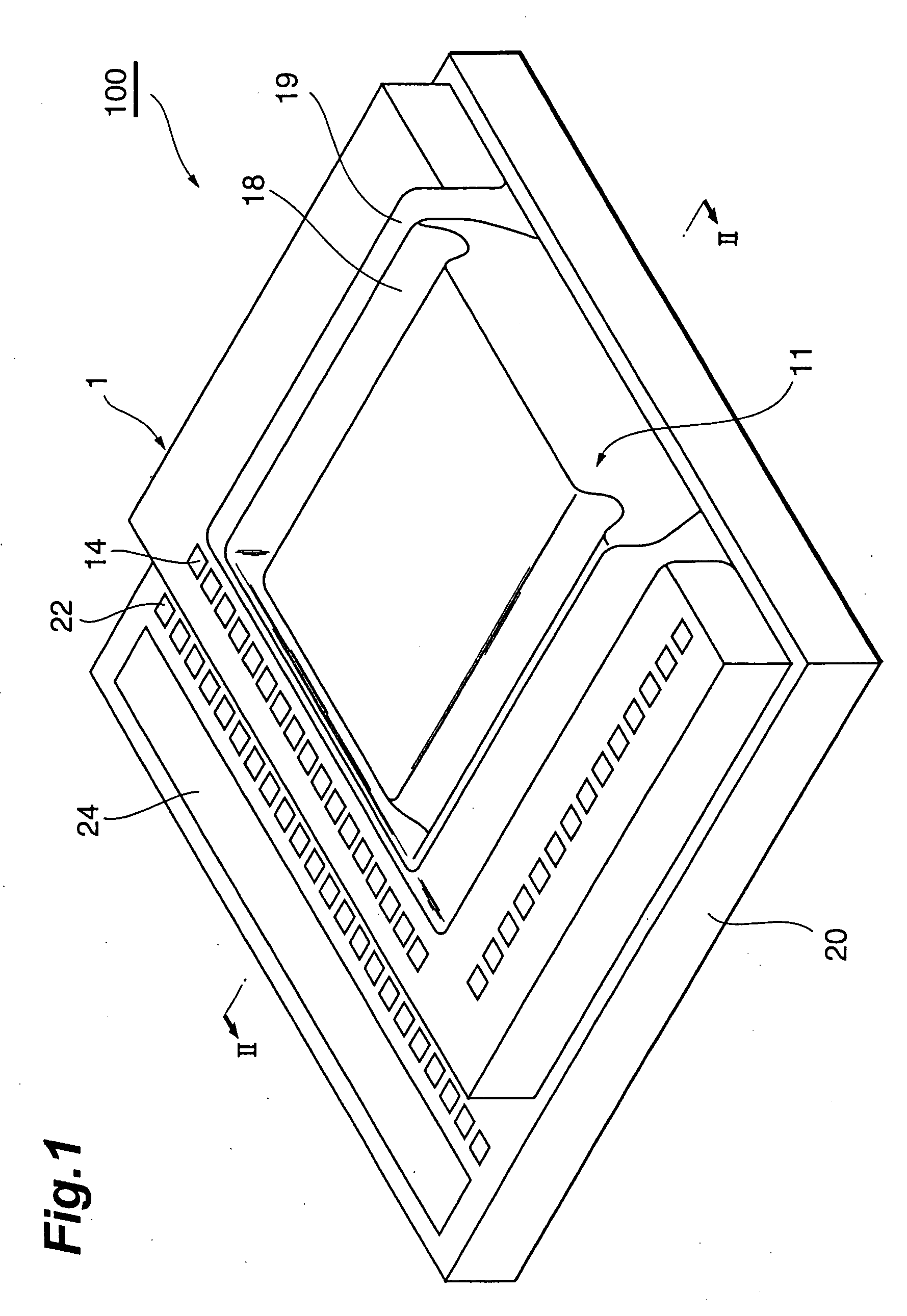
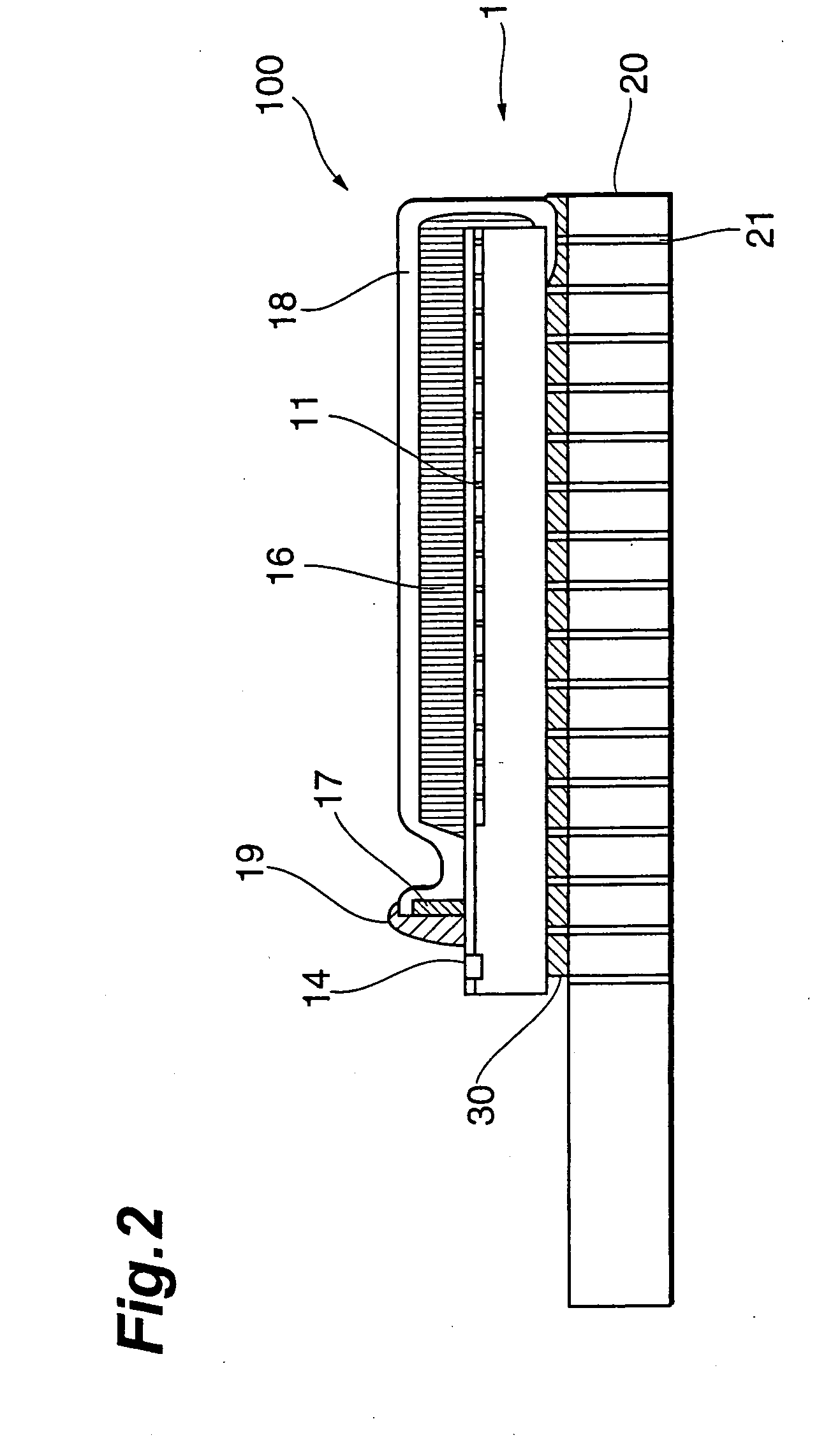
[0029]FIG. 1 is a front view showing a first embodiment of the radiation image sensor according to the present invention, and FIG. 2 a sectional view thereof. This radiation image sensor 100 is constructed in a configuration in which image sensor assembly 1 is mounted on mount substrate 20, and is one applied to mammography. FIG. 3 is a perspective view of image sensor assembly 1, FIG. 4 a front view thereof, FIG. 5 a sectional view thereof along line V-V, and FIG. 6 a sectional view thereof along line VI-VI.

[0030] In image sensor assembly 1, photodiodes for photoelectric conversion are two-dimensionally arranged to form light sensitive portion 11 as a light rece...


PUM


Abstract

An image sensor assembly is mounted and fixed on a mount substrate with an adhesive, and a light sensitive portion of the image sensor assembly is located so as to reach the vicinity of at least one peripheral region. A moisture-proof protective film to cover a scintillator layer of the image sensor assembly is laid so as to cover the scintillator layer over a side wall to which the light sensitive portion is in proximity, up to the back side of a substrate of the image sensor assembly, and this portion on the back side is sandwiched between the image sensor assembly and the mount substrate so as to be fixed.

Description

BACKGROUND OF THE INVENTION [0001] 1. Technical Field [0002] The present invention relates to a radiation image sensor for capturing a radiation image in the form of image data and, more particularly, to a radiation image sensor capable of detecting an image to an edge thereof, which is applied to mammography and others, and to a making method of them. [0003] 2. Background Art [0004] In the medical and industrial radiography, radiation imaging systems using a radiation detector instead of X-ray sensitive film have widely used in recent years. Such radiation imaging systems require no development as the X-ray sensitive film, are highly convenient, for example, in that one can check a radiation image in real time, and are also advantageous in terms of storageability of data and facility to handle. [0005] A common radiation imaging system is configured to convert an incident radiation image into visible light or the like (including ultraviolet and infrared rays) by a scintillator, to d...

Claims


Application Information

Patent Timeline
Patent Type & Authority Applications(United States)
IPC IPC(8): G01T1/20G01T1/29H01L27/146
CPCG01T1/2928H01L27/14663H01L27/14618H01L2924/0002H01L2924/00
Inventor SUGANUMA, MASAHIROSUZUKI, TAKAHARUMORI, HARUMICHIHONDA, MASAHIKOTAKABAYASHI, TOSHIO
Owner HAMAMATSU PHOTONICS KK
Learn More