Eureka AIR delivers breakthrough ideas for toughest innovation challenges, trusted by R&D personnel around the world.

Cavity electrode structure, and sensor and protein detection device using the same

a protein detection and cavity electrode technology, applied in the field of cavity electrode structure, can solve the problems of inability to use the introduction of fluorescent labels, requiring comparatively elaborate equipment, and difficult to precisely form electrodes with gap of several nanometers to several tens of nanometers

Inactive Publication Date: 2005-07-28
FUJITSU LTD
View PDF8 Cites 16 Cited by
  • Summary
  • Abstract
  • Description
  • Claims
  • Application Information

AI Technical Summary

Benefits of technology

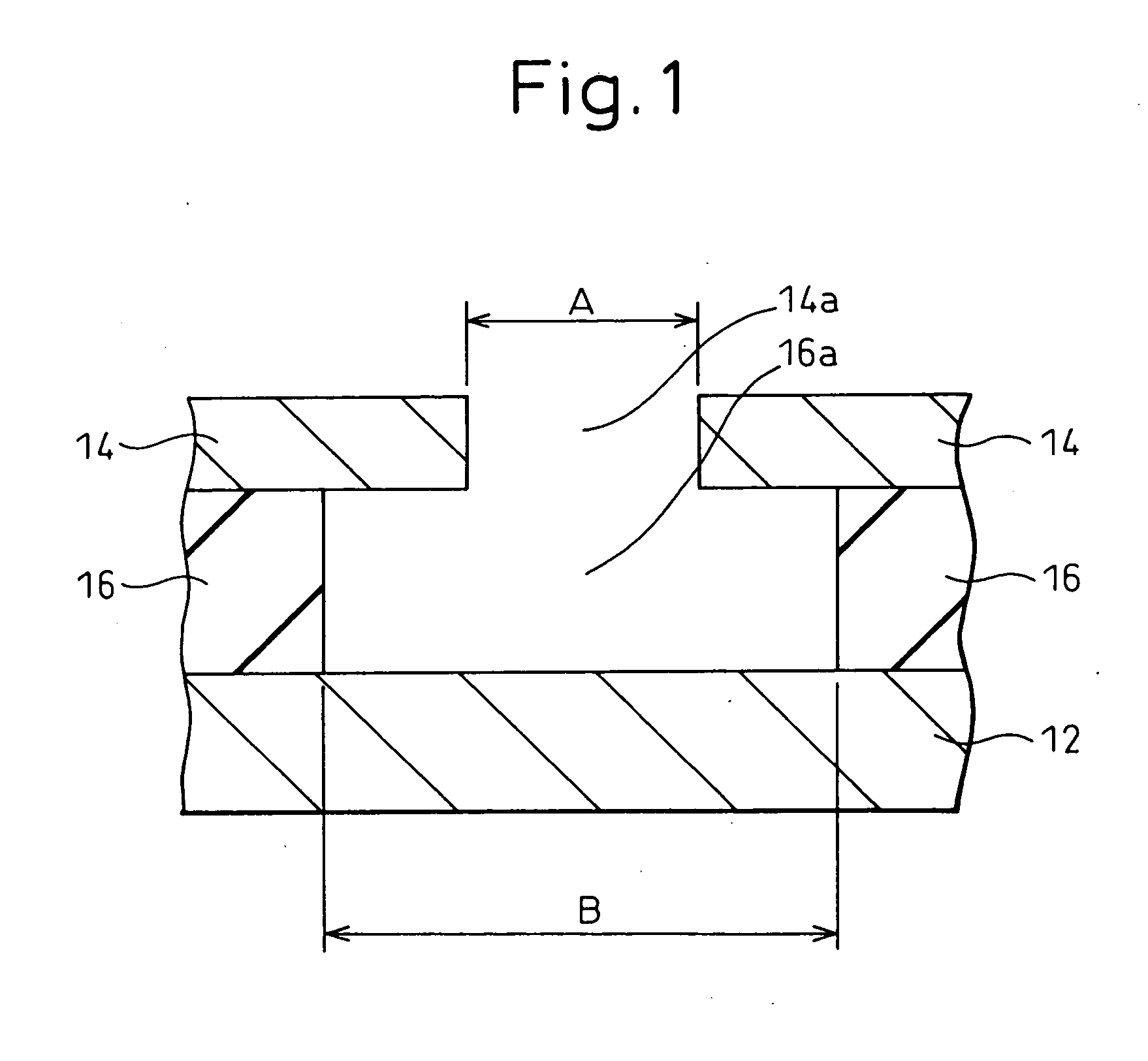
[0010] A cavity electrode structure of the present invention comprises: a first electrode, an insulating layer located on this first electrode and having a through hole that partially exposes the first electrode, and a second electrode opposed to the exposed surface of the first electrode by protruding towards the inside of the through hole of the insulating layer and provided with an opening that leads to the through hole of ...

Problems solved by technology

Although currently established measurement methods consist of combining two-dimensional electrophoresis and a mass analyzer, these require comparatively elaborate equipment.
In addition, in the case a protein is present in a sample as a mixture of numerous types of proteins, there was the problem of the uniform introduction of a fluorescent label being unable to be used due to differences in the reactivity between individual proteins and the pigment.
However, it has been extremely difficult to precisely form a pair of electrodes having a gap of several nanometers to several tens of nanometers equivalent to the size of DNA even with the use of leading-edge semiconductor processing technology.
There are many aspects of the structures of these sensors that are dependent on the spatial resolution of semiconductor photolithography processes of the prior art, and are therefore inadequate for handling biomolecules on the nanometer scale, while conversely the use of sophisticated devices results in exorbitant costs.

Method used


Image

  • Cavity electrode structure, and sensor and protein detection device using the same
  • Cavity electrode structure, and sensor and protein detection device using the same
  • Cavity electrode structure, and sensor and protein detection device using the same

Examples


embodiments

[0033] Although the following provides a more detailed explanation of the present invention with reference to its embodiments, the present invention is not limited to these embodiments.

[0034] In this embodiment, a protein detection device is explained that uses DNA attached with biotin that specifically binds to avidin protein.

[0035] A lower electrode layer 52 made of gold (Au), an insulating layer 54 made of SiO2, and an upper electrode layer 56 made of gold (Au) are sequentially formed (FIG. 4A) on a silicon substrate (not shown). The thickness of insulating layer 54 is made to be a thickness corresponding to the length of the DNA, for example 10 nanometers, that serves as the bridging member between the opposing electrodes. The thicknesses of lower and upper electrode layers 52 and 56 are made to be, for example, 0.1 micrometers and 0.1 micrometers, respectively. Next, as shown in FIG. 4B, a hole 56a (having a diameter of, for example, 50 micrometers) is formed by, for example,...


PUM


Abstract

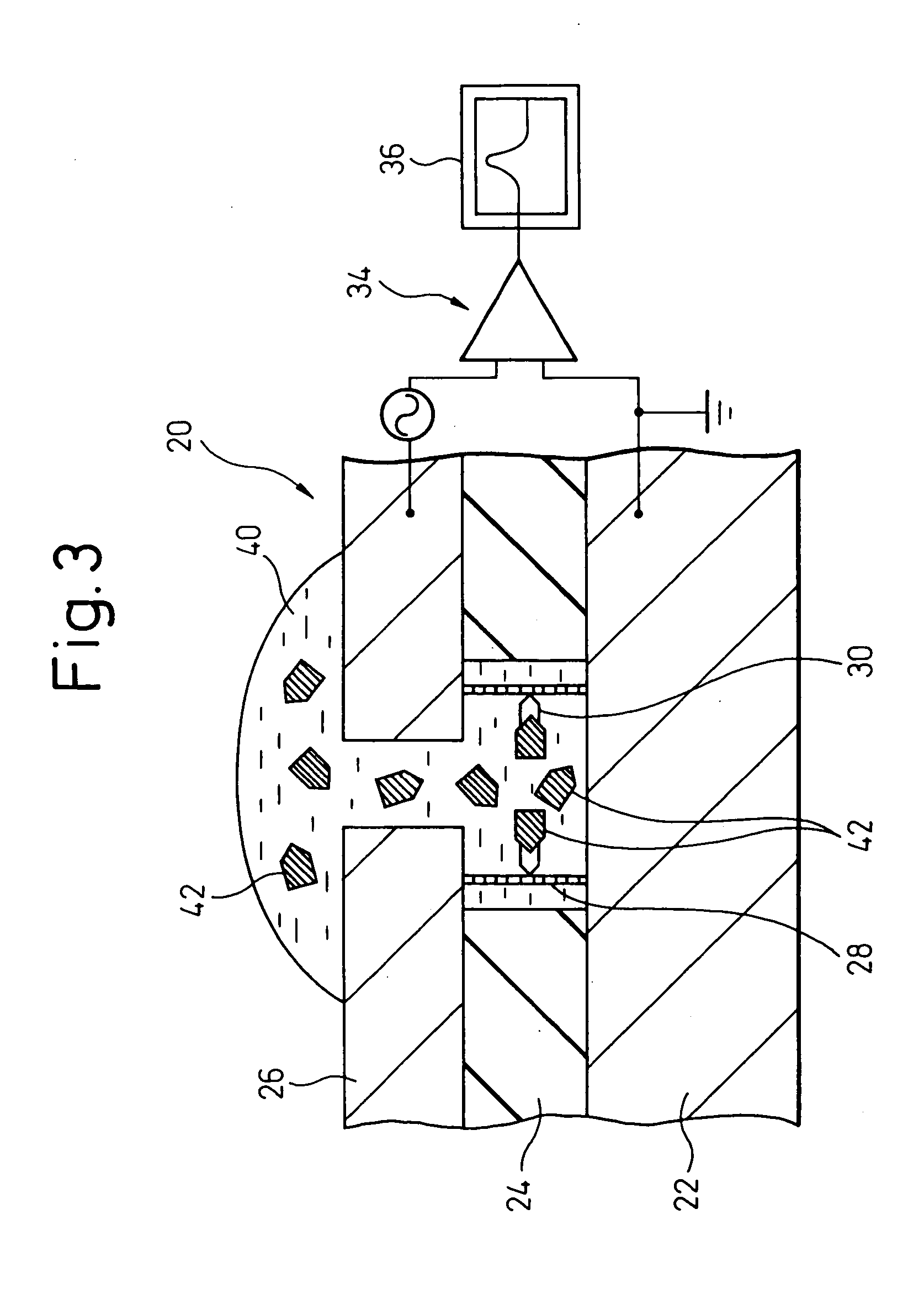
A cavity electrode structure, which is provided with a pair of opposing electrodes having a precisely formed narrow gap, and a sensor and a protein detection device, in which the cavity electrode structure is used, are provided. The cavity electrode structure comprises a first electrode, an insulating layer located on this first electrode and having a through hole that partially exposes the first electrode, and a second electrode opposed to the exposed surface of the first electrode by protruding towards the inside of the through hole of the insulating layer and provided with an opening that leads to the through hole of the insulating layer, the structure having a cavity that is formed by the exposed surface of the first electrode, the inner walls of the through hole of the insulating layer, and the surface of the second electrode that opposes the first electrode. The sensor comprises an electrically conductive bridging member of which one end is fixed to the exposed surface of the first electrode of the aforementioned cavity electrode structure, while the other end is fixed to the opposing surface of the second electrode, and which has a site that specifically binds to a target protein to be detected. The protein detection device uses a bridging member provided with a site that specifically binds to a target protein to be detected.

Description

CROSS-REFERENCE TO RELATED APPLICATION [0001] This application is a continuation application and is based upon PCT / JP03 / 04030, filed on Mar. 28, 2003.TECHNICAL FIELD [0002] The present invention relates to a cavity electrode structure provided with a pair of opposing electrodes having a narrow gap precisely formed without being restricted by the spatial resolution of a photolithography process, and a sensor and a protein detection device using the same. BACKGROUND ART [0003] Following its inception in the 1990s, various countries have shared the task of attempting to decipher all human gene codes, the results of which yielded the announcement of the completion of a draft of the human genome in the summer of 2000. The functions that are involved with each of the locations of the deciphered human genome sequence information are predicted to be identified in the future as a result of continuing progress in the areas of functional genome science and structural genome science. [0004] Thi...

Claims


Application Information

Patent Timeline
IPC IPC(8): C12M1/34G01N27/02G01N33/543
CPCG01N27/3278G01N33/5438
Inventor ARINAGA, KENJI
Owner FUJITSU LTD
Why Eureka
Eureka Blog
Learn More