
Video signal format secondary-conversion method, time code signal transmission method, and timecode transmitting apparatus

Active Publication Date: 2005-07-28
PANASONIC CORP
View PDF7 Cites 6 Cited by
  • Summary
  • Abstract
  • Description
  • Claims
  • Application Information

AI Technical Summary

Benefits of technology

[0014] Accordingly, in the present invention, the secondary conversion can be executed with the accurate knowledge of the relationship between the frame position and the time code in the format secondary conversion of the image signal.
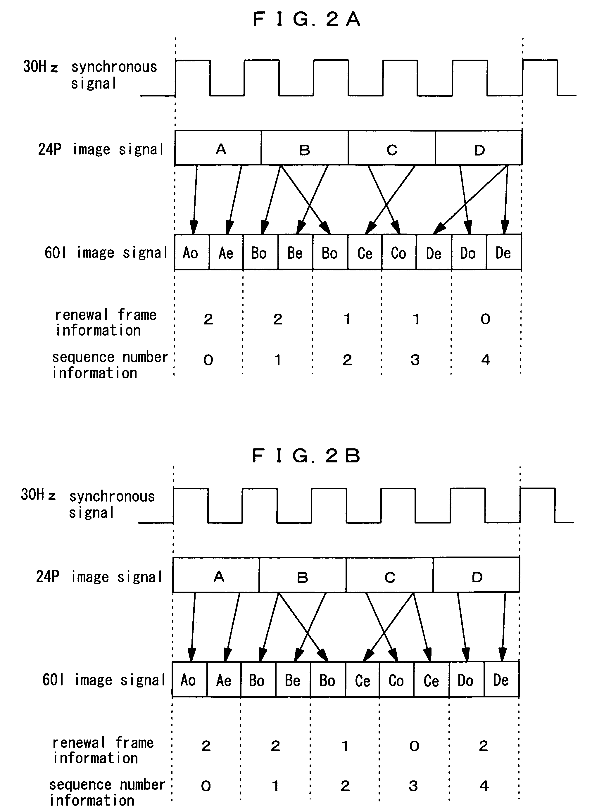
[0015] In the first time code signal transmission method, first time code signal transmission apparatus, and first format secondary conversion method for image signal according to the present invention, the information preferably represents a field position in the image signal where the image data is changed in the format conversion. In that manner, the secondary conversion can be executed while exactly knowing the relationship between the field position and the time code, and by extension, mutual conversions (primary and secondary conversions) between an interlace image signal and a progressive image signal can be executed with a high accuracy.

Problems solved by technology

However, a conventional technology has neither established any configuration where a relationship between the frame position and the time code signal can be accurately grasped nor proposed any effective method in the time code signal corresponding to the primary-converted image signal.

Method used


Image

  • Video signal format secondary-conversion method, time code signal transmission method, and timecode transmitting apparatus
  • Video signal format secondary-conversion method, time code signal transmission method, and timecode transmitting apparatus
  • Video signal format secondary-conversion method, time code signal transmission method, and timecode transmitting apparatus

Examples


Embodiment Construction

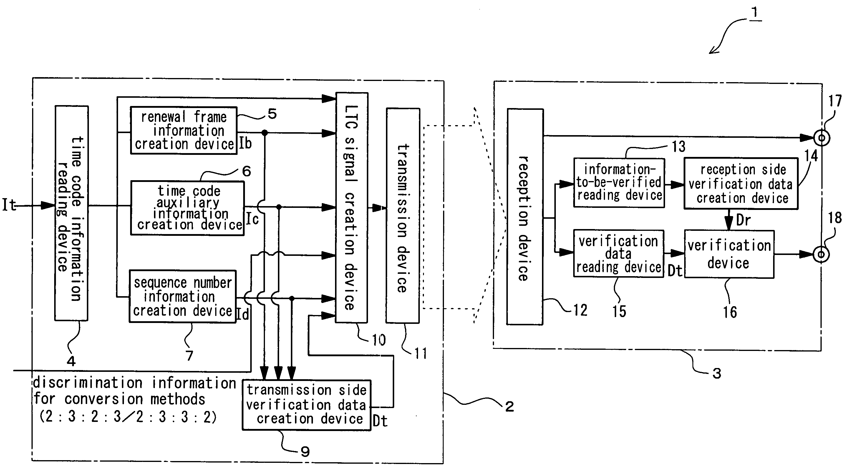
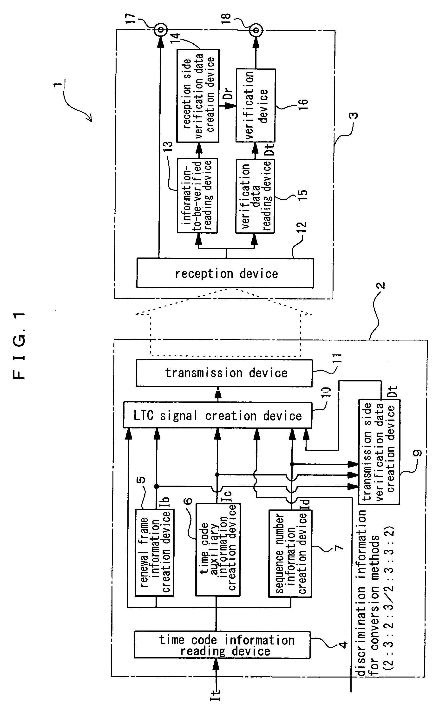
[0021] Hereinafter, a preferred embodiment of the present invention is described referring to the drawings. FIG. 1 is a block diagram illustrating a configuration of a time code signal transmission apparatus according to a preferred embodiment of the present invention. The present embodiment is premised on a format conversion of an image signal. In the present embodiment, the invention is realized by means of an apparatus for transmitting a time code signal corresponding to the format-converted image signal. To be more specific, the present embodiment is premised on a primary conversion of an image signal (hereinafter, referred to as 24P image signal) in a progressive format of 24 frames / second (hereinafter, referred to as 24P format) into an image signal (hereinafter, referred to as 60I image signal) in an interlace format of 30 frames / second (hereinafter, referred to as 60I format).

[0022] In the present embodiment, the invention is realized by means of a time code signal transmis...


PUM


Abstract

When a time code signal corresponding to an image signal, to which a format conversion changing the number of frames per second is executed, is transmitted, information indicating a frame position where image data is changed through the format conversion in the image signal is attached to the time code signal to be transmitted. Alternatively, information indicating a synchronous state between frame conversion cycles in the format conversion and time code progression is attached to the time code signal. In the fore going manner, a relationship between the frame position and the time code can be accurately grasped. Further, a secondary conversion (inverse conversion) is accurately executed to the image signal by means of the time code signal.

Description

TECHNICAL FIELD [0001] The present invention relates to a format secondary conversion method for an image signal, and a method and an apparatus for transmitting a time code signal used for the format secondary conversion method for the image signal. BACKGROUND OF THE INVENTION [0002] As a time code signal used for transmitting an image signal, LTC (Linear Time Code) signal subjected to a Biphasemark modulation and recorded in an audio frequency band can be mentioned. The time code signal is transmitted in a synchronous state with respect to the image signal. [0003] The advancement in an image technology in recent years has realized a format conversion of the image signal. In general, when the format conversion is executed, the number of frames per second is increased or decreased. More specifically, the format conversion processing results in increasing or decreasing the number of image data (hereinafter, referred to as frame image data) per second constituting the respective frames...

Claims


Application Information

Patent Timeline
IPC IPC(8): H04N7/01H04N7/08
CPCH04N7/01H04N7/08H04N7/0112
Inventor HOSODA, TAKAHARUURO, KATSUJISHIMAMURA, YUKIOUENO, MASAJI
Owner PANASONIC CORP
Learn More