
Satellite-positioning signal receiving device

Inactive Publication Date: 2005-07-28
DENSO CORP
View PDF3 Cites 30 Cited by
  • Summary
  • Abstract
  • Description
  • Claims
  • Application Information

AI Technical Summary

Benefits of technology

[0009] The present invention has been made with the above problems taken into account. It is an object of the present invention is to realize a receiving device that is of sm

Problems solved by technology

However, the present GPS receiving devices involve a problem.
To attain this object, there is a problem.
For this reason, a problem arises.
Another problem exists.
In high-latitude land areas, the number of satellites from which signals can be received is small, and the present position is often difficult to determine.

Method used


Image

  • Satellite-positioning signal receiving device
  • Satellite-positioning signal receiving device
  • Satellite-positioning signal receiving device

Examples


first embodiment

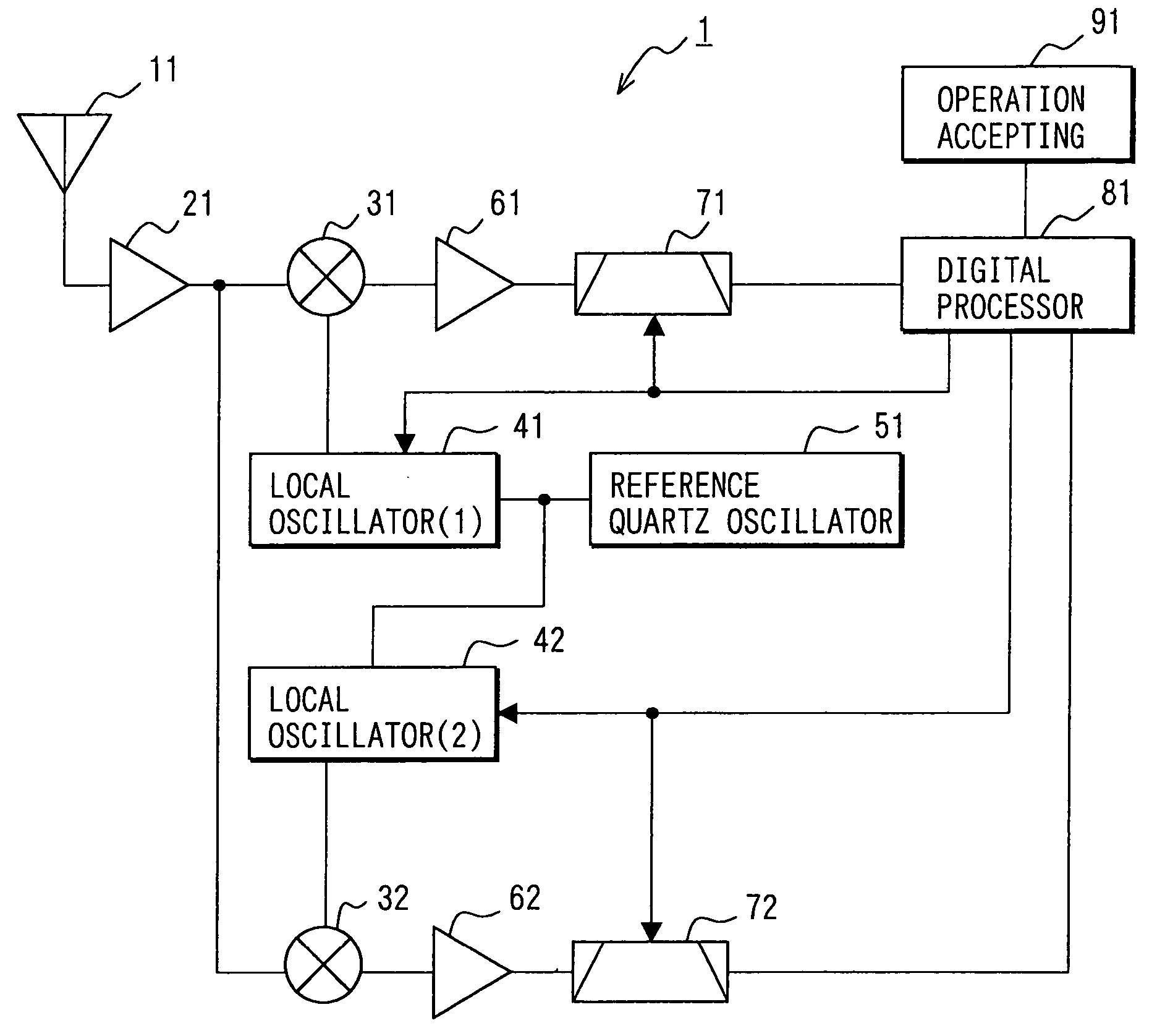
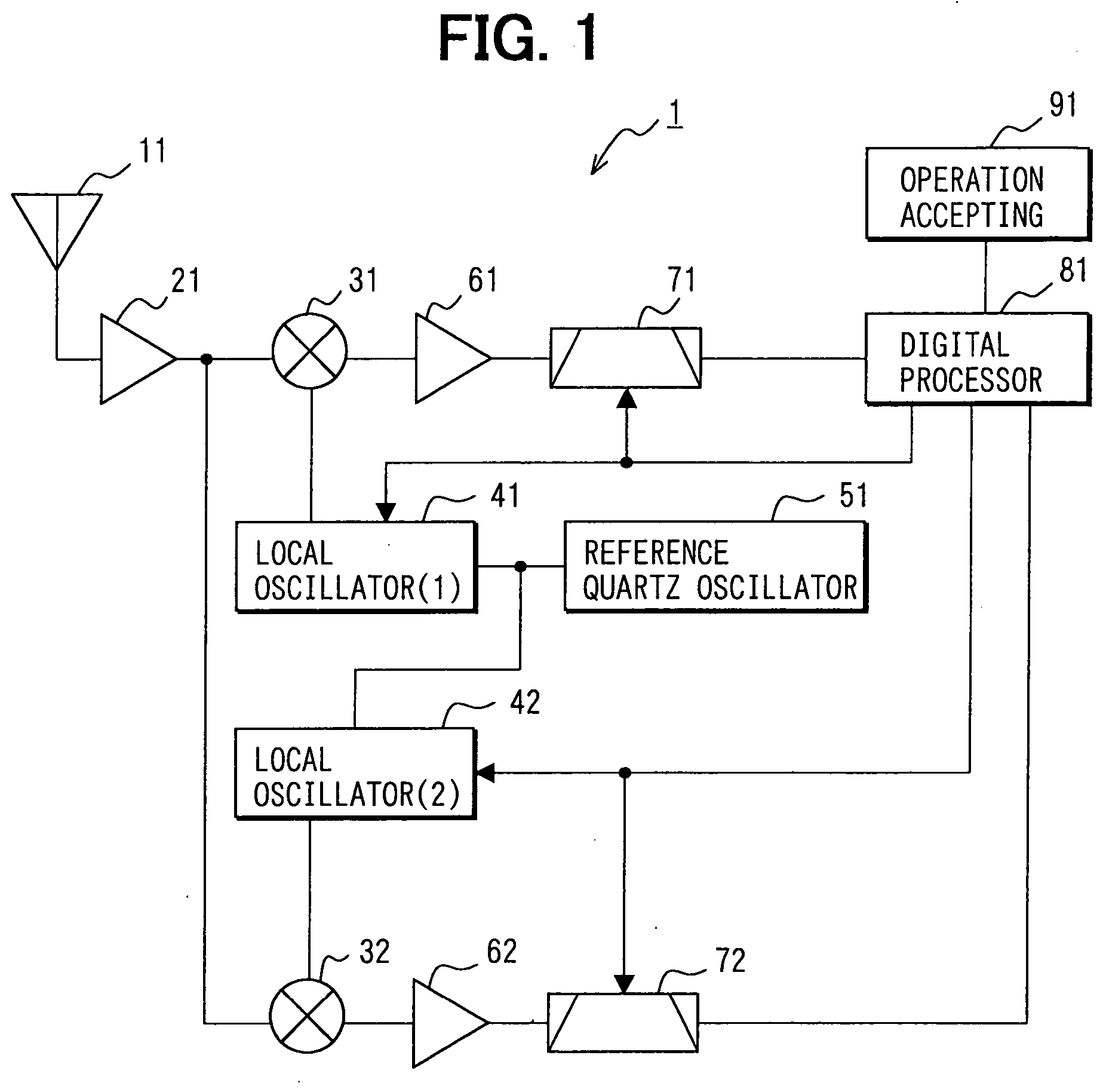
[0031]FIG. 1 is a block diagram illustrating a general constitution of a signal receiving device 1 for satellite positioning having two reception processing systems according to a first embodiment of the present invention.

[0032] The signal receiving device 1 for satellite positioning in this embodiment includes: an antenna 11 which receives signals from satellites; an RF amplifier unit 21 which amplifies the signals received by the antenna 11; a reference quartz oscillator 51; a digital processor unit 81 which performs signal processing; an operation accepting unit 91 which accepts the user's operation; and two reception processing systems, that is, a first reception processing system including a mixer unit (1) 31, a local oscillator (1) 41, an IF amplifier unit (1) 61, and an IF filter unit (1) 71, and a second reception processing system including a mixer unit (2) 32, a local oscillator (2) 42, an IF amplifier unit (2) 62, and an IF filter unit (2) 72. When the first reception pr...

second embodiment

[0081]FIG. 5 is a block diagram illustrating the general constitution of a signal receiving device 2 for satellite positioning having three reception processing systems.

[0082] This signal receiving device 2 for satellite positioning in the second embodiment is formed by adding a third reception processing system to the constitution of the signal receiving device 1 for satellite positioning in the first embodiment, illustrated in FIG. 1. The third reception processing system includes a mixer unit (3) 33, a local oscillator (3) 43, an IF amplifier unit (3) 63, and an IF filter unit (3) 73. The constitution of the second embodiment is the same as the signal receiving device 1 for satellite positioning in the first embodiment, excepting the third reception processing system.

[0083] Like the other local oscillators 41 and 42, the local oscillator (3) 43 in the third reception processing system is also connected to the reference quartz oscillator 51, and generates frequencies according t...


PUM


Abstract

A satellite-positioning receiving device includes: an antenna which receives a signal from a satellite; an RF amplifier unit which amplifies the signal received by the antenna; a reference quartz oscillator; a digital processor unit which performs signal processing; an operation accepting unit; and two reception processing systems, that is, a first reception processing system including a first mixer unit, a first local oscillator, a first IF amplifier unit, and a first IF filter unit and a second reception processing system including a second mixer unit, a second local oscillator, a second IF amplifier unit, and a second IF filter unit. The digital processor unit is connected to the local oscillators and the IF filter units, and is so constituted that it is capable of individually changing and setting their characteristics.

Description

CROSS REFERENCE TO RELATED APPLICATIONS [0001] This application is based on and incorporates herein by reference Japanese Patent Application No. 2004-14814 filed on Jan. 22, 2004. FIELD OF THE INVENTION [0002] The present invention relates to a device that receives a satellite-positioning signal corresponding to each of multiple satellite-positioning signal kinds. BACKGROUND OF THE INVENTION [0003] A global positioning system (GPS) is widely known as a system for positioning, for example, in car navigation systems. The GPS is a positioning system so designed that the apparent distances between GPS satellites and a GPS receiving device are measured and the position of the receiving device is computed. (For example, refer to Patent Document 1.) This receiving device receives 1575.42 MHz signals designated as L1. Signals of 1227.6 MHz and 1176.45 MHz will be available in the future, respectively, as a second signal (L2C) for civilian applications and a third signal (L5C) for civilian a...

Claims


Application Information

Patent Timeline
IPC IPC(8): G01S19/23G01S19/24G01S19/25G01S19/27G01S19/32G01S19/33G01S19/37
CPCG01S19/32G01S19/46G01S19/33
Inventor KATO, KOJI
Owner DENSO CORP
Learn More