Spindle device with state monitoring, and monitoring method and monitoring system therefore

Active Publication Date: 2005-07-28
WEISS SPINDELTECHNOLOGIE GMBH
View PDF7 Cites 15 Cited by
  • Summary
  • Abstract
  • Description
  • Claims
  • Application Information

AI Technical Summary

Benefits of technology

[0010] According to another feature of the present invention, the first physical variable and / or the second physical variable may each represent a distance traveled, speed, acceleration, or a particular direction component. This makes it possible to detect vibrations of the spindle which are generated by eccentricity or spindle components. The determination of directional components of the vibrations is especially advantageous to allow targeted maintenance works.
[0013] According to another feature of the present invention, the spindle device may include a memory for temporarily storing data of the first sensor and the at least one second sensor, and a controller for processing the data. Suitably, the first sensor and the at least one second sensor as well as the memory and the controller are integrated in a measuring ring which is disposed in proximity of one spindle bearing. In this way, the diagnosis assembly can easily be integrated in the spindle while the spindle in turn can be individually configured for providing the diagnosis data.
[0014] According to another feature of the present invention, the spindle device may include a classification unit for rating the condition of the spindle device in response to data from the first sensor and the at least one second sensor. In this way, classification may be carried out not only externally in a central diagnosis station but directly in the spindle so that data transfer rates can be reduced. The classification may, however, also be carried out internally or externally in dependence on the respective system load.

Problems solved by technology

This learning process is time-consuming and produces a limit value for only a single spindle type in a particular machine and possibly for only a single particular manufacturing operation.
This type of limit value determination is thus unsuitable for operation of primary spindles and other production machines.

Method used


Image

  • Spindle device with state monitoring, and monitoring method and monitoring system therefore
  • Spindle device with state monitoring, and monitoring method and monitoring system therefore
  • Spindle device with state monitoring, and monitoring method and monitoring system therefore

Examples


Embodiment Construction

[0026] Throughout all the Figures, same or corresponding elements are generally indicated by same reference numerals. These depicted embodiments are to be understood as illustrative of the invention and not as limiting in any way. It should also be understood that the drawings are not necessarily to scale and that the embodiments are sometimes illustrated by graphic symbols, phantom lines, diagrammatic representations and fragmentary views. In certain instances, details which are not necessary for an understanding of the present invention or which render other details difficult to perceive may have been omitted.

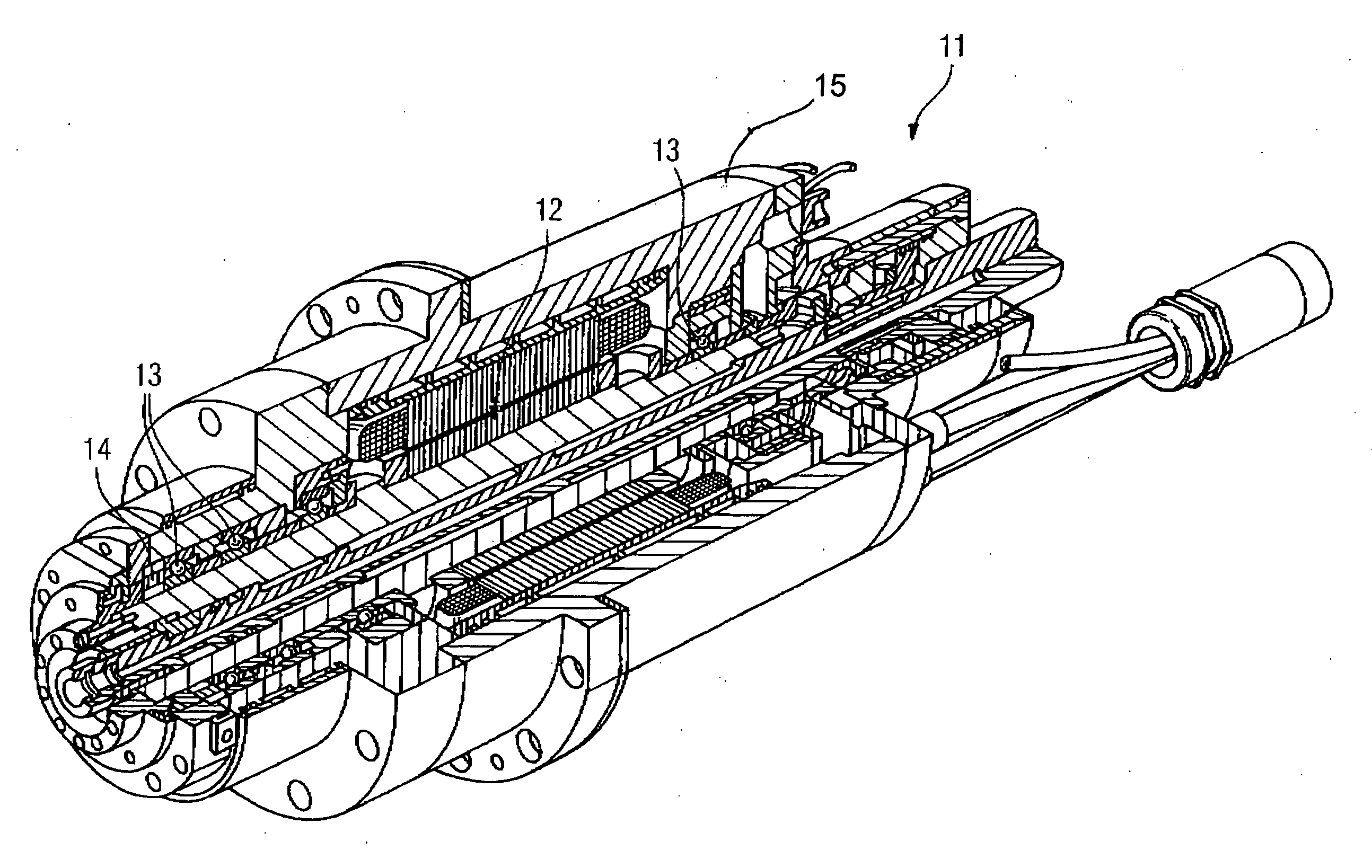
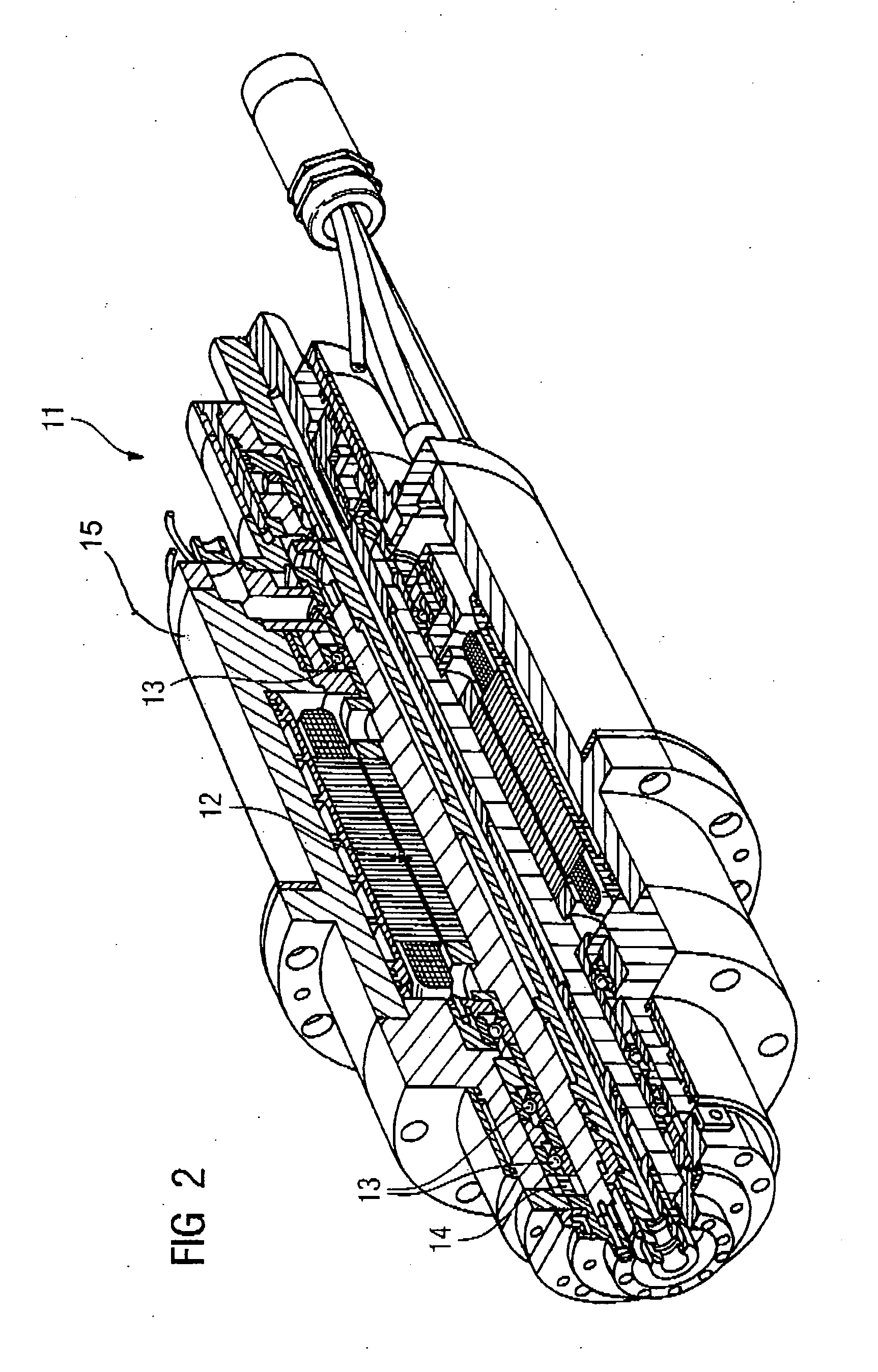
[0027] Turning now to the drawing, and in particular to FIG. 2, there is shown a longitudinal section of a motor spindle according to the present invention, generally designated by reference numeral 11. The motor spindle includes a rotor 12 which is supported by bearings 13 in a spindle housing 15. Disposed immediately adjacent to one of the bearings 13 (here, by way of exam...


PUM

PropertyMeasurementUnit
Timeaaaaaaaaaa
Temperatureaaaaaaaaaa
Speedaaaaaaaaaa

Abstract

A spindle device for driving a production machine includes a first sensor for detecting a first physical variable of the spindle device, and at least a second sensor for detecting a second physical variable of the spindle device. In this way, it becomes possible to determine the oscillation amplitude of the rotor of a spindle and a temperature profile of a rolling bearing. Monitoring maximum values allows identification of a crash event, whereas the temperature profile allows conclusions as to a need for maintenance. Signal evaluation can take place centrally at the spindle manufacturer's end, thereby allowing needed maintenance works to be planned long term and effectively.

Description

CROSS-REFERENCES TO RELATED APPLICATIONS [0001] This application claims the priority of German Patent Application, Serial No. 103 48 608.9, filed Oct. 20, 2003, pursuant to 35 U.S.C. 119(a)-(d), the disclosure of which is incorporated herein by reference. BACKGROUND OF THE INVENTION [0002] The present invention relates to a spindle device for operating a production machine. The present invention further relates to a monitoring system for monitoring at least one such spindle device, as well as to a method of operating a spindle device. [0003] Nothing in the following discussion of the state of the art is to be construed as an admission of prior art. [0004] Increase in productivity is a primary goal for the manufacturing industry and the stimulus for optimization and development in the field of production planning and process technique. It is therefore of great importance to operate a primary spindle as effective as possible for a production machine, e.g. a milling machine or a lathe....

Claims


Application Information

Patent Timeline
IPC IPC(8): B23Q5/04B23Q17/10B23Q17/12
CPCB23Q5/04B23Q17/10Y10T74/18688F16C19/52B23Q17/12F16C2322/39
Inventor WALTER, RUDOLF
Owner WEISS SPINDELTECHNOLOGIE GMBH
Why Eureka
Try Eureka