
Rotating machine

Inactive Publication Date: 2005-07-21
JATCO LTD
View PDF0 Cites 16 Cited by
  • Summary
  • Abstract
  • Description
  • Claims
  • Application Information

AI Technical Summary

Benefits of technology

[0003] However, the metal plating formed on the permanent magnet is for preventing the corrosion of the permanent magnet, and never gains the advantage of preventing a so-called induction heating of the permanent magnet by such metal plating having the thickness ranging from 3 to 20 μm.
[0005] The basic magnetic flux is static with respect to a permanent magnet rotating in synchronism with the rotating magnetic field and exhibits the direct-current like behavior. Therefore, the basic magnetic flux does not cause induction heating. On the other hand, the high-frequency magnetic flux tends to penetrate into a permanent magnet due to a high-frequency component thereof. Specifically, in case of a rare-earth permanent magnet made by an electro-conductive sintered body, it is difficult to avoid the generation of Joule heat according to the eddy current reaction function against the high-frequency magnetic field. That is, induction heat is unavoidably generated in the rare-earth permanent magnet so as to lower the output of the rotating machine including the permanent magnet in a reversible demagnetization range according to temperature and to lose the magnetic properties in an irreversible demagnetization range according to temperature.
[0006] It is therefore an object of the present invention to provide an improved rotating machine which solves the problems about the induction heating, in addition to the prevention of the corrosion into the rare-earth permanent magnet.
[0007] The inventor of the present invention intensively researched a loss generation mechanism of a rare-earth magnet coated with metal plating whose thickness is greater than 3 μm and smaller than or equal to 20 μm, and found that it became possible to solve the problems about the induction heating of the rare-earth permanent magnet by adjusting the thickness of metal plating on the surface of the permanent magnet so as to prevent the permeation of the high-frequency magnetic flux into the magnet while preventing the corrosion of the magnet.

Problems solved by technology

However, the metal plating formed on the permanent magnet is for preventing the corrosion of the permanent magnet, and never gains the advantage of preventing a so-called induction heating of the permanent magnet by such metal plating having the thickness ranging from 3 to 20 μm.
Specifically, in case of a rare-earth permanent magnet made by an electro-conductive sintered body, it is difficult to avoid the generation of Joule heat according to the eddy current reaction function against the high-frequency magnetic field.
That is, induction heat is unavoidably generated in the rare-earth permanent magnet so as to lower the output of the rotating machine including the permanent magnet in a reversible demagnetization range according to temperature and to lose the magnetic properties in an irreversible demagnetization range according to temperature.

Method used


Image

  • Rotating machine
  • Rotating machine
  • Rotating machine

Examples


Embodiment Construction

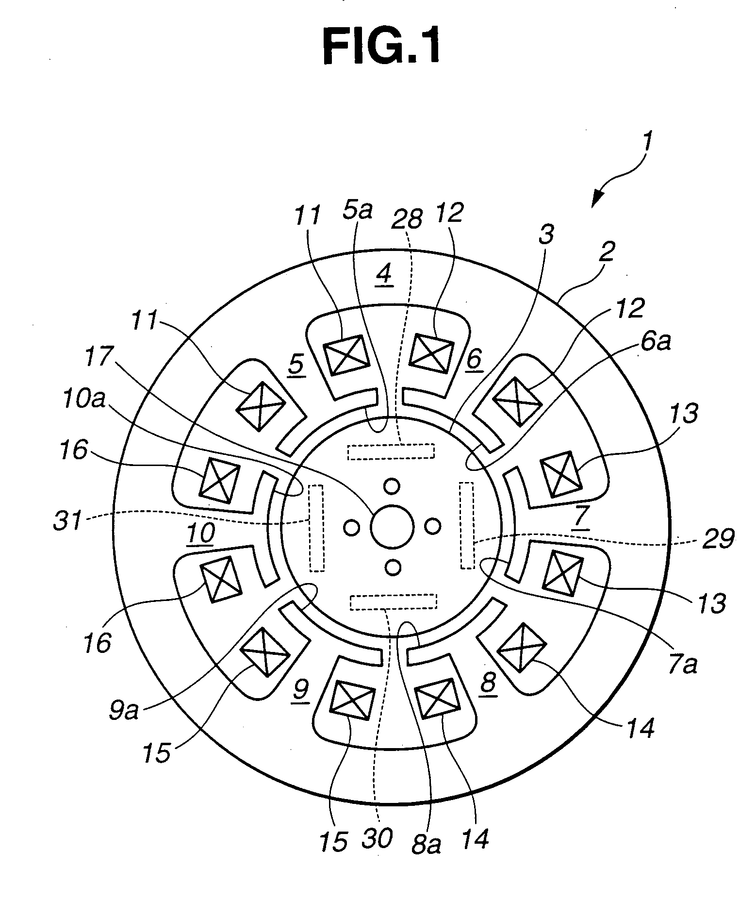
[0016] Referring to FIGS. 1 through 5, there is discussed an embodiment of a permanent magnet synchronous machine 1 according to the present invention.

[0017] As shown in FIG. 1, permanent magnet synchronous machine (rotating machine) 1 comprises a stator 2 and a rotor 3. Stator 2 comprises a cylindrical yoke 4 and teeth 5 through 10 which radially and inwardly project from an inner surface of cylindrical yoke 4 at equal intervals. Cylindrical yoke 4 and teeth 5 through 10 are integrally formed from a magnetic material such as silicon steel sheets. Stator windings 11 through 16 are wound around teeth 5 through 10, respectively.

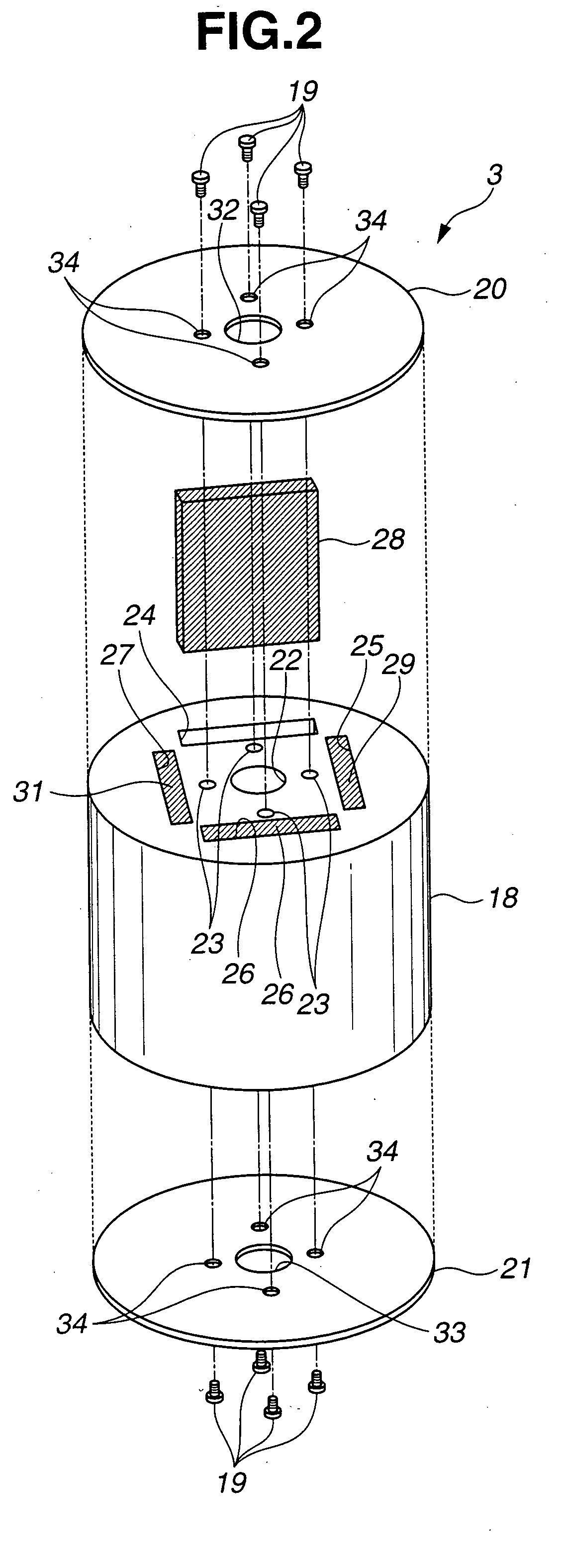
[0018] Rotor 3 is a cylindrical rotating member which has a shaft fixed at a center of rotor 3. Rotor 3 is disposed in a space defined by stator 2 such that rotor 3 is capable of rotating in stator 2 while maintaining a predetermined distance with respect to innermost ends 5a through 10a of teeth 5 through 10.

[0019] As shown in FIG. 2, rotor 3 comprises a cy...


PUM


Abstract

A rotating machine is comprised of a rotor having permanent magnets and a stator disposed around the rotor. At least a surface of the permanent magnet, which faces the stator, is covered with a magnetic material whose thickness is determined on the basis of an electrical conductivity of the magnetic material, a magnetic permeability of the magnetic material and a frequency of a high-frequency magnetic flux act from the stator on the rotor.

Description

BACKGROUND OF THE INVENTION [0001] The present invention relates to a rotating machine, and more particularly to a rotating machine comprising a rotor including a permanent magnet. [0002] Japanese Published Patent Application No. 2000-324738 discloses a rotating machine which comprises a rotor including a rare-earth-alloy permanent magnet made by a sinter alloy of rare earth metal, such as Sm—Co alloy or Nd—Fe—B alloy. Further, Japanese Published Patent Application No. 6-140217 discloses a technique of coating a rare-earth-alloy permanent magnet with metal plating whose thickness is greater than 3 μm and smaller than or equal to 20 μm, for the purpose of preventing a corrosion of the permanent magnet. SUMMARY OF THE INVENTION [0003] However, the metal plating formed on the permanent magnet is for preventing the corrosion of the permanent magnet, and never gains the advantage of preventing a so-called induction heating of the permanent magnet by such metal plating having the thicknes...

Claims


Application Information

Patent Timeline
IPC IPC(8): H02K1/22H02K1/27H02K7/09H02K21/02H02K21/12H02K21/16
CPCH02K21/02H02K1/276
Inventor ENDO, KENJI
Owner JATCO LTD
Learn More