
Method and device for detecting a fiber lap as well as a fiber cutting machine

a cutting machine and fiber lap technology, applied in the direction of mechanical roughness/irregularity measurement, instruments, nuclear elements, etc., can solve the problems of lap development, entrapment or destruction, and the optical method and device of this type is very susceptible to malfunction

Inactive Publication Date: 2005-07-14
SAURER GMBH & CO KG
View PDF3 Cites 0 Cited by
  • Summary
  • Abstract
  • Description
  • Claims
  • Application Information

AI Technical Summary

Benefits of technology

[0010] To obtain a high monitoring sensitivity, an advantageous further development of the invention provides for directing the sensor signal substantially perpendicularly to the circumferential surface of the rotating component. With that, it is possible to form a focused monitoring range on the circumference of the rotating component. Additionally, by combining the ultrasonic transmitter and the sound receiver to a structural unit, a very compact sensor unit is created, which can be excellently shielded against external influences.
[0011] In the case of a constantly predetermined spacing between the sensor unit and the rotating component, it is possible to generate a difference signal directly from the variation between an actual transit time and a predetermined desired transit time of switching signals. To this end, an advantageous further development of the invention provides for measuring the actual transit time from transmitting the sensor signal until receiving the echo sound signal, and for comparing it with the predetermined desired transit time that defines the situation without fiber laps. Thus, the difference signal that is determined from the variation directly contains information about the presence of a fiber lap.
[0012] To achieve shutdown times that are as short as possible, or to avoid damage to the component, the difference signal can be used for directly releasing a control command or for generating an alarm signal. To this end, the sensor unit is advantageously coupled via an interface with a process control unit or a machine control unit.
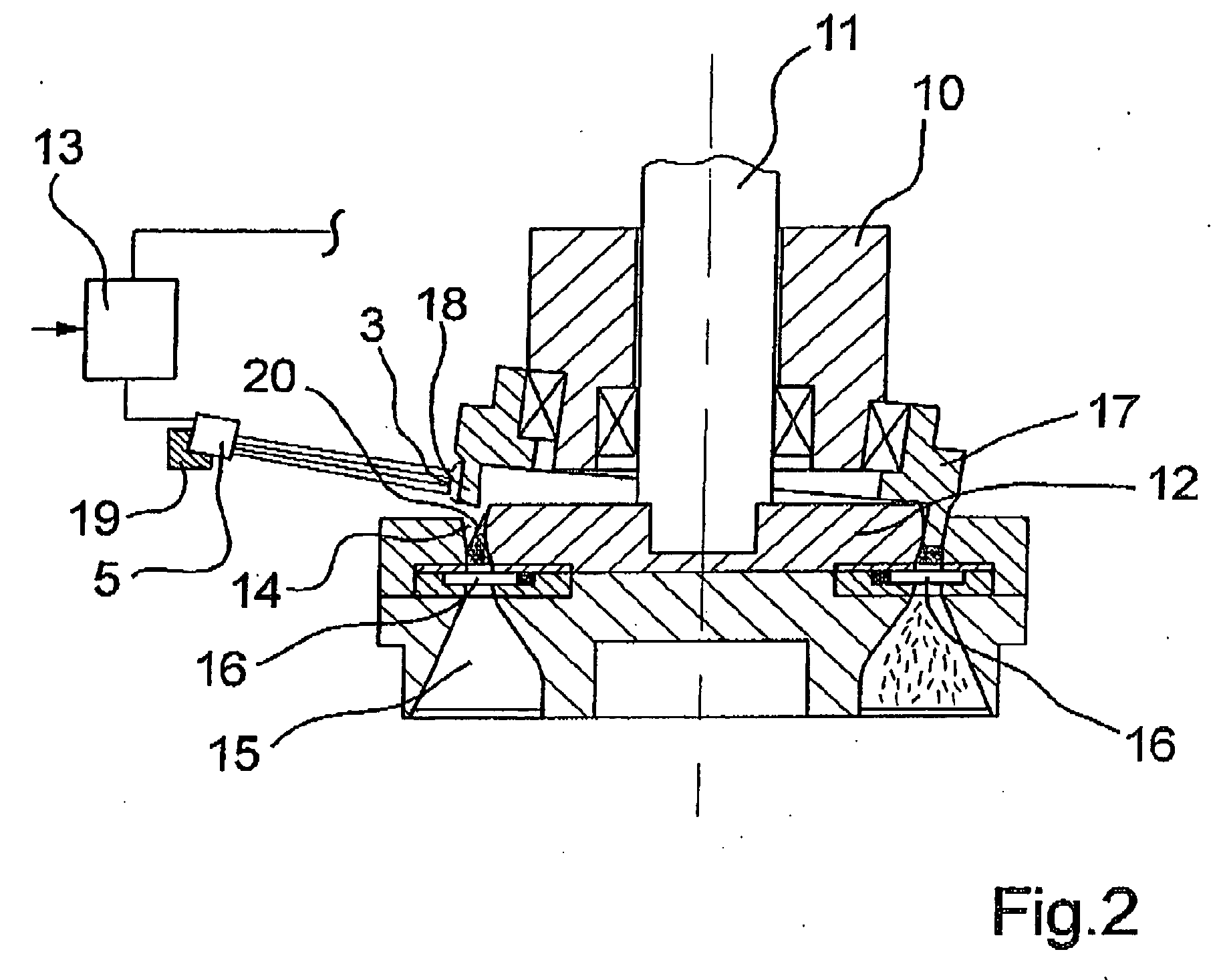
[0014] Because of the flexible arrangement of the sensor units as well as the insensitivity of the sensor signals, the invention is especially suited for detecting tows. In particular in so-called fiber cutting machines, breakdowns may occur during the cutting process in such a manner that the continuous tow enters the cutting space of the machine in an unclean manner. This may cause laps to form on the rotating components of the machine, which require a direct intervention into the cutting process. In the case of a fiber cutting machine of the invention, it is thus possible to monitor laps directly on the circumference of a pressure ring, which supports the tow as it enters the cutting space.
[0015] In this connection, it is advantageous to couple the sensor unit directly with the machine control unit, so that same causes the fiber cutting machine to shut down upon detection of a lap.

Problems solved by technology

As soon as fiber strands advance in contact with or in the vicinity of such rotating components, there basically arises the problem that so-called laps may develop.
However, optical methods and devices of this type are very susceptible to malfunction, since soiling of transmitters and receivers, as well as flying lint lead to frequent error detections.
Devices of this type, however, have the problem that the sensing element can get caught in the loops and irregularities of the fiber strands and that it can be entrained or be destroyed.
In addition, joints, springs, and microswitches make the mechanical setup cost intensive as well as susceptible to wear.

Method used


Image

  • Method and device for detecting a fiber lap as well as a fiber cutting machine
  • Method and device for detecting a fiber lap as well as a fiber cutting machine
  • Method and device for detecting a fiber lap as well as a fiber cutting machine

Examples


Embodiment Construction

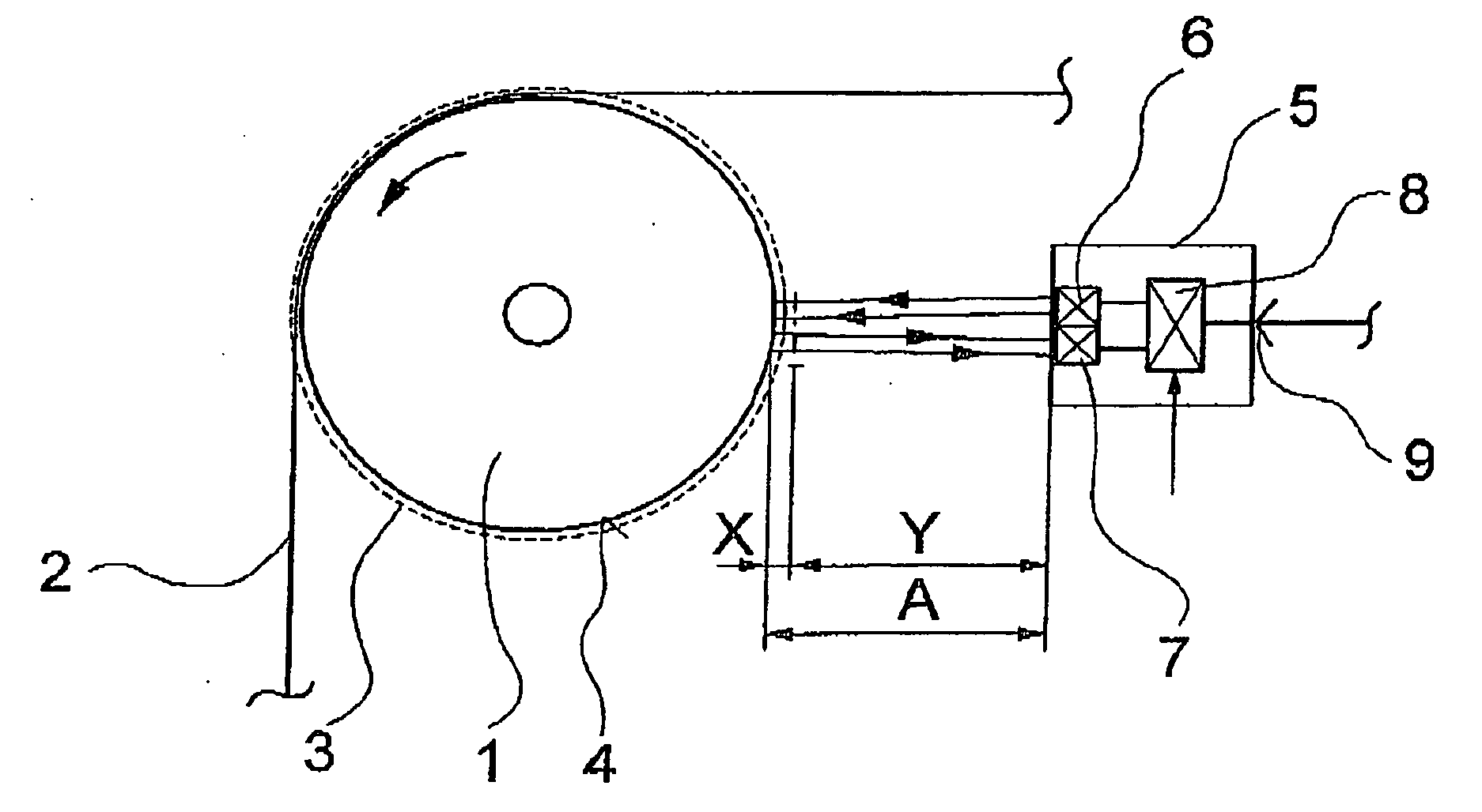
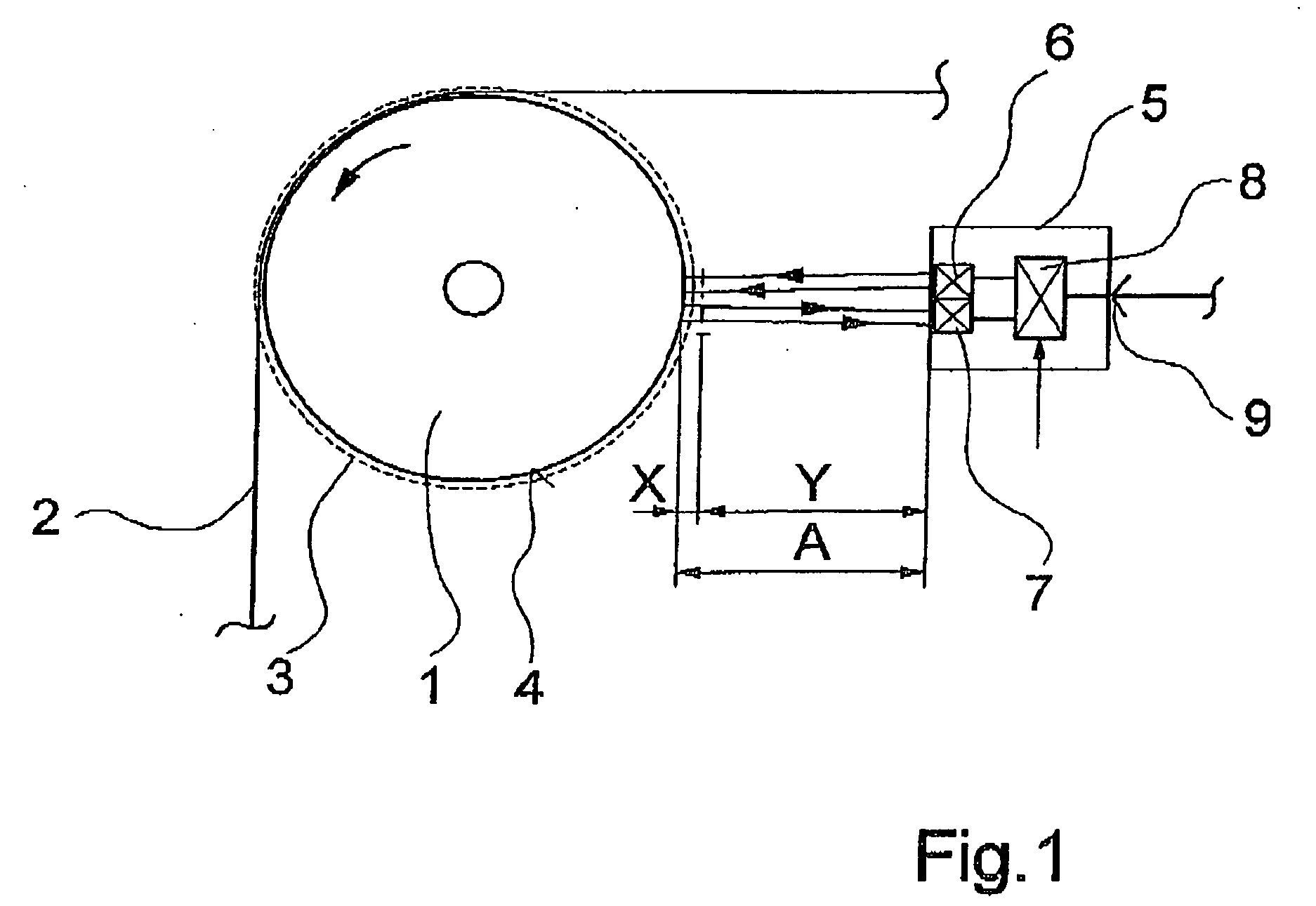
[0019]FIG. 1 schematically illustrates a first embodiment of a device according to the invention for carrying out the method of the invention for detecting a fiber lap.

[0020] The device comprises a sensor unit 5, which is arranged at a distance A from a rotating component. The rotating component is shown as a roll 1, which is supported for rotation. On a circumferential surface 4 of the roll 1 a fiber strand 2 advances while partially looping the roll. The sensor unit 5 is arranged substantially in spaced relationship with the looping range of the fiber strand 2 on the roll 1.

[0021] The sensor unit 5 comprises an ultrasonic transmitter 6 and a sound receiver 7, which are combined to a structural unit. The ultrasonic transmitter 6 and the sound receiver 7 connect to an electronic evaluation unit 8. Via an interface 9, the sensor unit 5 connects to a process control unit not shown.

[0022] In the embodiment shown in FIG. 1, the fiber strand 2 could be formed, for example, by a yarn, ...


PUM

PropertyMeasurementUnit
distanceaaaaaaaaaa
diameteraaaaaaaaaa
diameteraaaaaaaaaa

Abstract

A method and a device for detecting a fiber lap on a rotating machine component, wherein a sensor signal is used to detect the fiber lap that has formed on the circumference of the component. To enable a noncontacting monitoring despite unfavorable environmental conditions, the sensor signal comprises ultrasound, and an echo sound signal is evaluated to detect the presence of a fiber lap. In one disclosed embodiment, the detecting device is used in association with a fiber cutting machine for cutting tow, and which comprises a rotating cutting blade holder and a rotatable pressure ring, which cooperate for cutting the tow. To achieve a shutdown of the machine as quickly as possible upon formation of a fiber lap, the fiber lap is directly monitored on the circumference of the pressure ring by means of a sensor unit which has an ultrasonic transmitter and a sound receiver.

Description

BACKGROUND OF THE INVENTION [0001] The present invention relates to a method and device for detecting a fiber lap on a rotating machine component, as well as a fiber cutting machine which includes the device. [0002] When treating and processing strandlike fibers, the latter advance over or through rotationally symmetric components, which may be used, for example, as rolls for drawing, as feed systems for advancing, as pressure rolls, drive rolls, or pressure rings in fiber cutting machines. As soon as fiber strands advance in contact with or in the vicinity of such rotating components, there basically arises the problem that so-called laps may develop. In such cases, adhesive forces entrain the fiber strands on the circumference of the rotating component and wrap it around the component. Formations of such fiber laps must be rapidly detected to avoid long shutdown times or even destruction of the components. [0003] To this end, methods and devices are known, wherein the circumferent...

Claims


Application Information

Patent Timeline
Patent Type & Authority Applications(United States)
IPC IPC(8): B65H63/00D01G1/00B65H63/04B65H63/06D06H3/10D06H7/00G01S15/04G01S15/10G01S15/88
CPCB65H63/003B65H2701/31G01S15/88G01S15/10G01S15/04B65H63/06
Inventor STREBE, MATTHIAS
Owner SAURER GMBH & CO KG
Learn More