Method and device for emitting and/or receiving information relating to a vehicle

Inactive Publication Date: 2005-07-14
ROBERT BOSCH GMBH
View PDF19 Cites 80 Cited by
  • Summary
  • Abstract
  • Description
  • Claims
  • Application Information

AI Technical Summary

Benefits of technology

[0003] Communication of mobile terminal devices with stationary computers in the Internet via standardized communications paths, for example, via the WAP protocol, allows telematics terminals that are provided with a suitable access and are already present in the vehicle to be used for performing vehicle-related telematics applications, such as remote query and / or remote control of vehicle components and / or for performing remote diagnostics, without requiring a complete redesign of these terminal devices and the corresponding expenditure.
[0005] A further positive effect of using this protocol is that resources such as memory and computing power are reduced in the terminal devices because this protocol is specifically designed for terminal devices with few resources. When using this protocol, no additional functional units are needed for data transmission and content visualization. This is accomplished only by using a WAP browser, which is available, and the associated WAP communication stack. In terms of reducing resources in the terminal device, the use of the WAP protocol is especially beneficial if the WAP protocol is present in the terminal device anyway for other services such as mobile Internet. Thus, the synergy achieved by using this protocol is considerable.
[0007] It is a particular advantage that the WAP standard provides an interface (EFI interface) which allows the WAP browser (and thus indirectly the server) to communicate with independent external applications on the mobile terminal device via a standardized functional interface. Thus, mechanisms are provided that facilitate communication with software components which are not included in the browser, such as the diagnostics interface to the control units to be diagnosed.
[0008] A particular advantage is that, in addition to the above-mentioned vehicle-related telematics applications, such as remote diagnosis of vehicle control units, it is also possible to implement further telematics services via the standardized protocol, such as breakdown call, emergency call, or traffic information.
[0011] The use of a protocol standard that is adapted to mobile applications (such as WAP) shows particularly beneficial results in conjunction with telematics services in motor vehicles over mobile radio networks.

Problems solved by technology

Thus, the synergy achieved by using this protocol is considerable.

Method used


Image

  • Method and device for emitting and/or receiving information relating to a vehicle
  • Method and device for emitting and/or receiving information relating to a vehicle
  • Method and device for emitting and/or receiving information relating to a vehicle

Examples


first embodiment

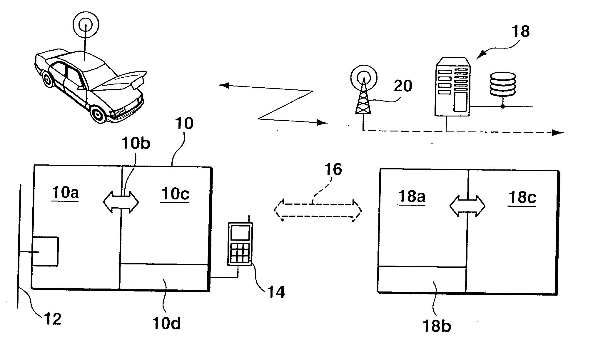
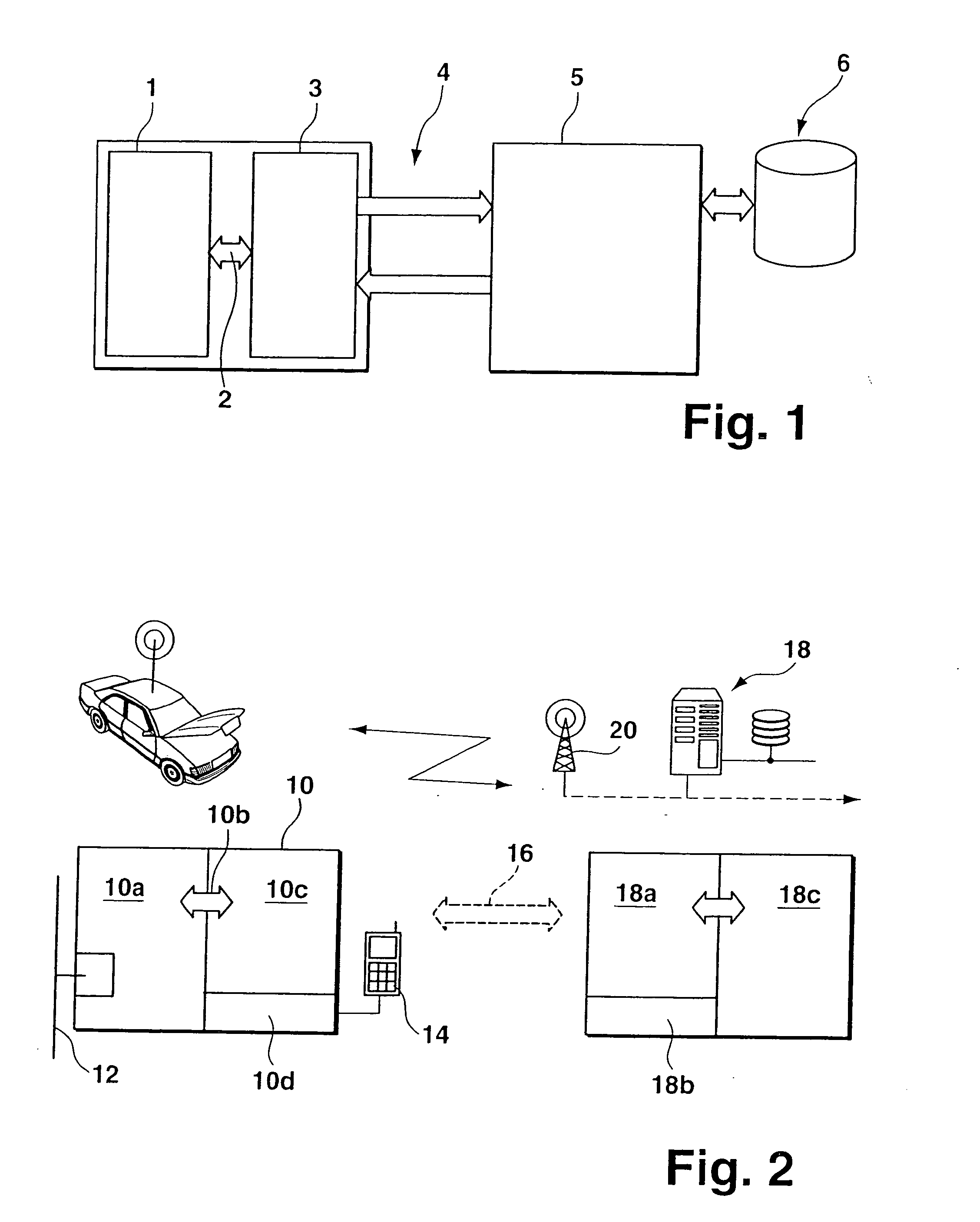
[0035] The contents or data that are relevant for remote diagnostics and which, in addition to the actual diagnostic data, also contain commands for the control and configuration of the remote diagnostics functionality integrated in the vehicle, are structured differently, depending on the variant. In a first embodiment, the remote diagnostics unit in the vehicle contains mechanisms and functions for performing the diagnostic procedures independently. Error memories of the control units are read out for data acquisition via remotely controlled functions in the telematics terminal device. The telematics terminal device contains functional units such as the transport protocol layer for CAN bus data, the protocol layer required for the logical diagnostic process, as well as a suitable sequence control.

second embodiment

[0036] In this connection, the required data for the respective protocol layers and for the sequence control may be downloaded from the diagnostics server at the beginning of the diagnostic process, and that the layers be configured using protocol macros and communications parameters. As a consequence, it may be necessary to also transmit parameters and diagnostic macros in addition to the actual control commands for remotely controlling the remote diagnostic functions. Moreover, the data required for parametrization is always permanently kept available in the telematics terminal device, which eliminates the need to transmit this data from the server to the client. A second embodiment proposes to transmit commands at the level of the diagnostic protocol. In this case, the unit in the vehicle does not perform the diagnostic process independently, but only passes the data coming from the server through to the control unit to be diagnosed. Thus, diagnostic protocol functionalities in t...

third embodiment

[0037] This means for the data contents transmitted during the diagnostic process that, in addition to the actual diagnostic data (fault memory contents), diagnostic commands that are specified, for example, according to the KWP 2000 diagnostic protocol standard, are transmitted as well. A third embodiment uses mixed forms of the two described, extreme variants of partitioning diagnostic functions between the telematics terminal device and the service center. For example, commands for remote control of the overall functions and individual commands of the diagnostic protocol that are not permanently integrated in the terminal device are transmitted in parallel.

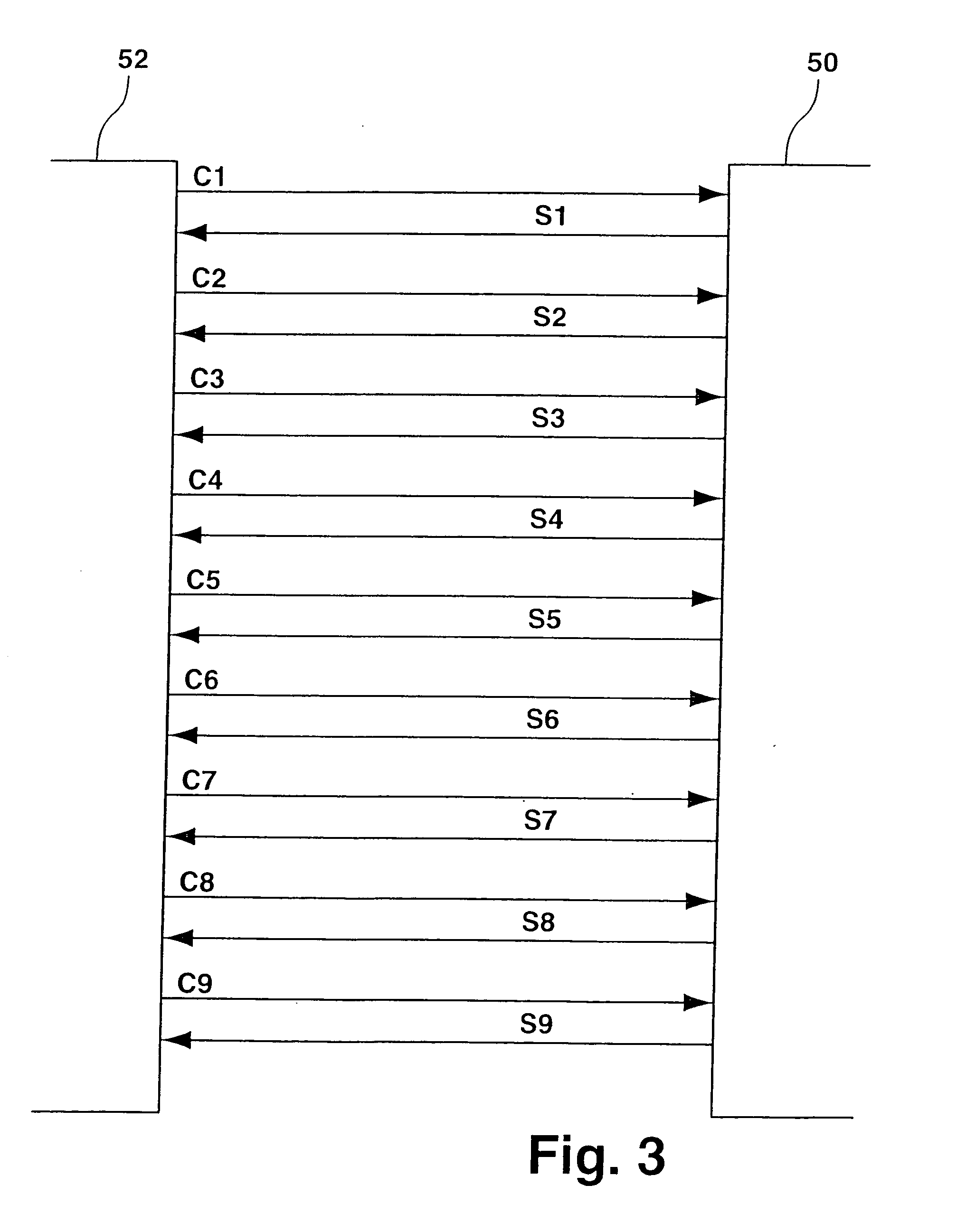
[0038] In the representation of FIG. 3, on-board portion 52 of the diagnostic system is shown on the left, while network portion 50 is shown on the right. The arrows represent the flow of information, the chronological order of the requests and responses during the communication being shown from top to bottom. In this connectio...


PUM


Abstract

A method and device for transmitting, sending and / or receiving information in conjunction with a vehicle. Information used for implementing vehicle-related remote monitoring being transmitted via a mobile radio network. In this connection, the communication takes place on the basis of a standardized protocol that is adapted to the conditions of the mobile radio network, which may be the WAP protocol.

Description

FIELD OF THE INVENTION [0001] The present invention relates to a method and device for transmitting, sending and / or receiving information in conjunction with a vehicle, in particular, for remote diagnostics, remote control and / or remote operation of a component / function of the vehicle. BACKGROUND INFORMATION [0002] A method and device for transmitting, sending and / or receiving information in conjunction with a vehicle is discussed in German patent document no. 100 26 754. In order to implement remote maintenance, remote diagnostics and / or remote control of a motor vehicle, of one of its components and / or functions, data is exchanged via a telecommunications network and / or a data network. A mobile radio network according to GSM or UMTS standard is proposed as an example for the telecommunications network while the Internet is mentioned as an example for the data network. No reference is made to the specific embodiment, in particular, with respect to the flexibility and / or reliability...

Claims


Application Information

Patent Timeline
IPC IPC(8): B60R16/023B60R16/02G05B15/02G05B23/02G07C5/00G08G1/09H04L12/413
CPCH04L67/025G07C5/008
Inventor SONNENREIN, THOMASBAUER, NORBERT
Owner ROBERT BOSCH GMBH
Why Eureka
Try Eureka