Piezoelectric switch for tunable electronic components
a technology of electronic components and piezoelectric switches, which is applied in the direction of piezoelectric/electrostrictive device details, device details, generators/motors, etc., can solve the problems of inability to achieve substantial reduction in the size of these switches, increase response time, and relatively low production costs, so as to reduce the lateral dimension, reduce the actuation voltage, and reduce the effect of lateral dimension
- Summary
- Abstract
- Description
- Claims
- Application Information
AI Technical Summary
Benefits of technology
Problems solved by technology
Method used
Image
Examples
first embodiment
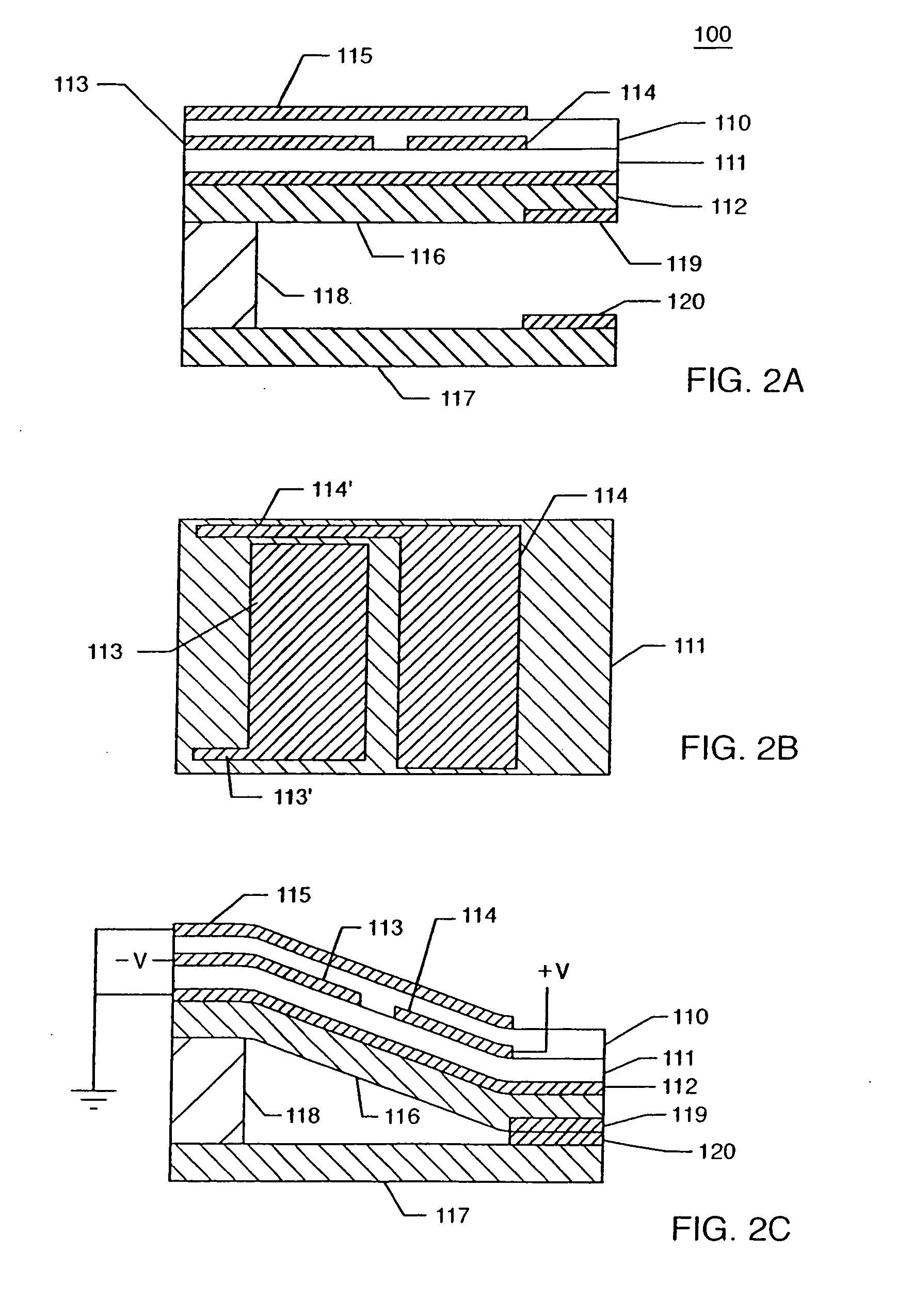
[0037]FIGS. 2A-2C show a switch according to the present invention. The switch, generally designated 100, is fabricated on a substrate 117 using generally known microfabrication techniques, such as masking, etching, deposition, and lift-off. In a preferred embodiment, the switch 100 is directly formed on the substrate 117. Alternatively, the switch 100 may be discreetly formed and then bonded to the substrate 117.
[0038] The switch 100 comprises an upper piezoelectric layer 110, a lower piezoelectric layer 111, a first electrode 112 placed under the lower layer 111, a second electrode 113 placed between the upper layer 110 and the lower layer 111, a third electrode 114 placed between the upper layer 110 and the lower layer 111, a fourth electrode 115 placed above the upper layer 110, and a Si3N4 layer 116 placed under the electrode 112. In the preferred embodiment, shown in the figure, the electrode 112 extends along the whole length of the piezoelectric layer 111, in order to avoid ...
third embodiment
[0068]FIGS. 7A-7B show a switch according to the present invention, where only three electrodes are used, and cross voltages are applied to the upper and lower electrodes.
[0069]FIG. 7A shows a switch 300 comprising an upper piezoelectric layer 310, a lower piezoelectric layer 311, a first or lower electrode 312 placed under the lower layer 311, a second or middle electrode 313 placed between the upper layer 310 and the lower layer 311, and a third or upper electrode 315 placed above the upper layer 310. A Si3N4 layer 316 is connected to the electrode 312 and placed under the electrode 312. The switch 300 is placed above a substrate 317 and spaced from the substrate 317 by means of a spacer 318. Additionally, a first contact pad 319 is provided under the second electrode 312 and a second contact pad 320 is provided above the substrate 317.
[0070] Also in the third embodiment, an ‘S’ shaped deformation or deflection is obtained upon application of a voltage, as shown in FIG. 7B. The ‘...
fourth embodiment
[0072]FIGS. 8A-8C show a switch according to the present invention, where switching occurs according to a combination between electrostatic effect and piezoelectric effect. In particular, combination of the electrostatic effect with the embodiment of FIGS. 7A and 7B is shown.
[0073]FIG. 8A shows a switch 400 comprising an upper piezoelectric layer 410, a lower piezoelectric layer 411, a first or lower electrode 412 placed under the lower layer 411, a second or middle electrode 413 placed between the upper layer 410 and the lower layer 411, and a third or upper electrode 415 placed above the upper layer 410. A Si3N4 layer 416 is connected to the electrode 412 and placed under the electrode 412. The switch 400 is placed above a substrate 417 and spaced from the substrate 417 by means of a spacer 418. Additionally, a first contact pad 419 is provided under the second electrode 412 and a second contact pad 420 is provided above the substrate 417. The distance between contact pads 419 and...
PUM
| Property | Measurement | Unit |
|---|---|---|
| distance | aaaaa | aaaaa |
| actuation voltages | aaaaa | aaaaa |
| actuation voltage | aaaaa | aaaaa |
Abstract
Description
Claims
Application Information
 - R&D
- Intellectual Property
- Life Sciences
- Materials
- Tech Scout
- Unparalleled Data Quality
- Higher Quality Content
- 60% Fewer Hallucinations
Browse by: Latest US Patents, China's latest patents, Technical Efficacy Thesaurus, Application Domain, Technology Topic, Popular Technical Reports.
© 2025 PatSnap. All rights reserved.Legal|Privacy policy|Modern Slavery Act Transparency Statement|Sitemap|About US| Contact US: help@patsnap.com


