
Invertedly driven electrostatic speaker

Inactive Publication Date: 2005-07-07
TRANSPARENT SOUND TECH
View PDF6 Cites 17 Cited by
  • Summary
  • Abstract
  • Description
  • Claims
  • Application Information

AI Technical Summary

Benefits of technology

[0011] We have invented an improved electrostatic speaker system which overcomes the major deficiencies seen in prior art electrostatic speakers. Our electrostatic speakers do not require that a high voltage AC audio signal be applied to the stators. Accordingly, the chance of electrical shock by touching the stator is essentially eliminated.
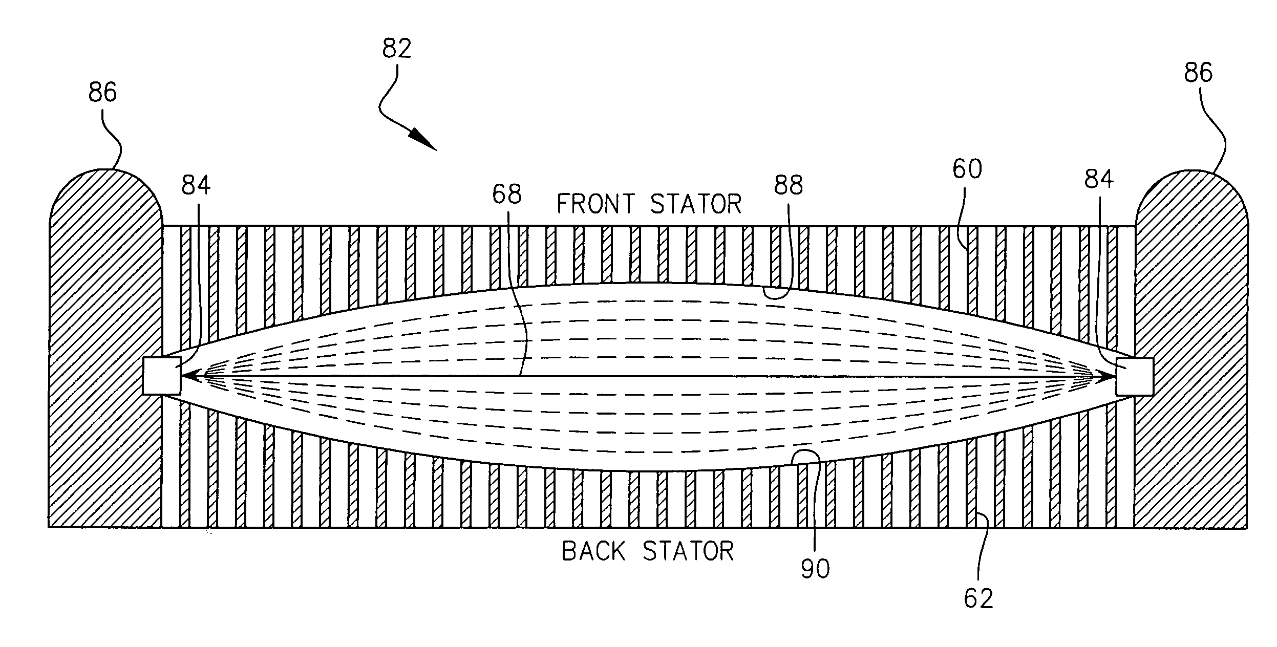
[0013] In the preferred embodiment, a pair of (front and back) stator plates are used and a thin sheet of electrically conductive film (the diaphragm) is disposed there between. The diaphragm has a high resistive value and is coupled to a high voltage audio power transformer in an audio signal electrical circuit. Low impedances are avoided for the speaker and a more desirable 4 ohm load can be run on the invertedly driven electrostatic speaker system of the present invention. Traditional 1 ohm loads, used on prior art electrostatic speaker systems, are avoided.
[0014] The diaphragm of our invertedly driven electrostatic speaker system is acoustically filtered, wherein low pass filtering is applied to one side of the film separating the high and mid frequencies thereby avoiding a beaming radiating panel and providing a wider and longer disbursement of the sound waves emanating from each speaker panel.
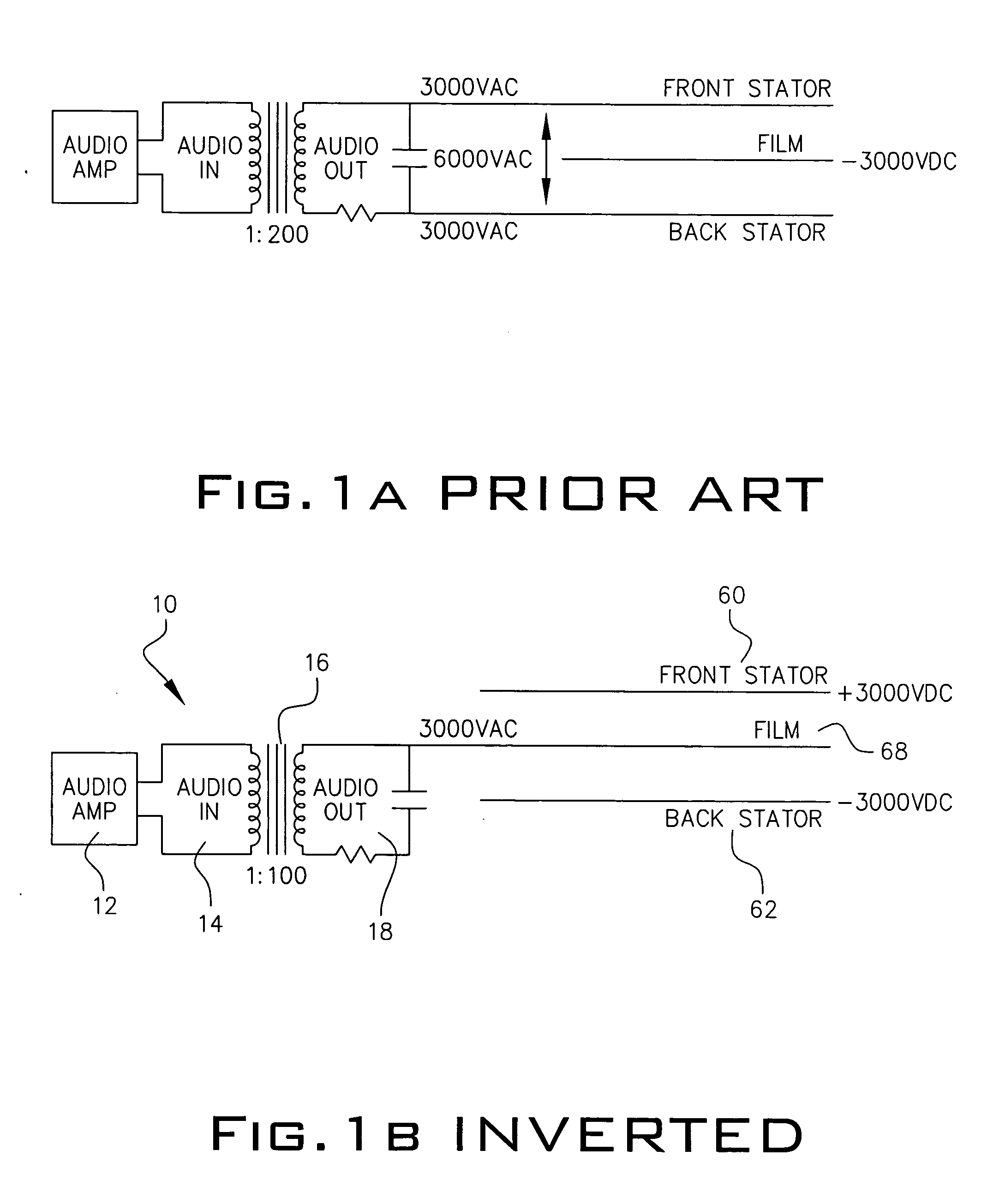
[0015] Most importantly, even though a high voltage AC audio signal is being applied to the diaphragm and not the stators directly, approximately one-quarter of the typically applied amount of audio high voltage is needed using our novel invertedly driven electrostatic speaker system. This allows for a more simple and less expensive audio amplifier to be used to drive our speakers as compared to the power needs for driving prior art electrostatic speakers. This translates into a safer electrostatic speaker system, which is more efficient than any speaker the prior art, all the while providing a speaker having a greater frequency response.

Problems solved by technology

The high voltage AC audio signal applied to the stators of prior art electrostatic speaker systems can be dangerous if touched or punctured.
So much so, that Applicant is unaware of any known electrostatic speaker system that has received a UL (Underwriters Laboratories®) safety standard listing, which requires that high voltages not be present in electronic devices, which can easily shock or electrocute users of the c device.
The use of high voltage AC audio signals on prior art electrostatic speaker systems has been a hindrance to the manufacturers of these known electrostatic speaker systems and has prohibited them from receiving UL® approval.
Prior art electrostatic speaker systems also require exotic, stable and very powerful, and more often than not, very expensive amplifiers (preferably tube amplifiers) to drive them and to perform well as designed.
This need stems from the very low impedance requirements (values) of the speaker at very high frequencies, resulting in heavy loads being applied to the audio amplifier driving the electrostatic speaker.
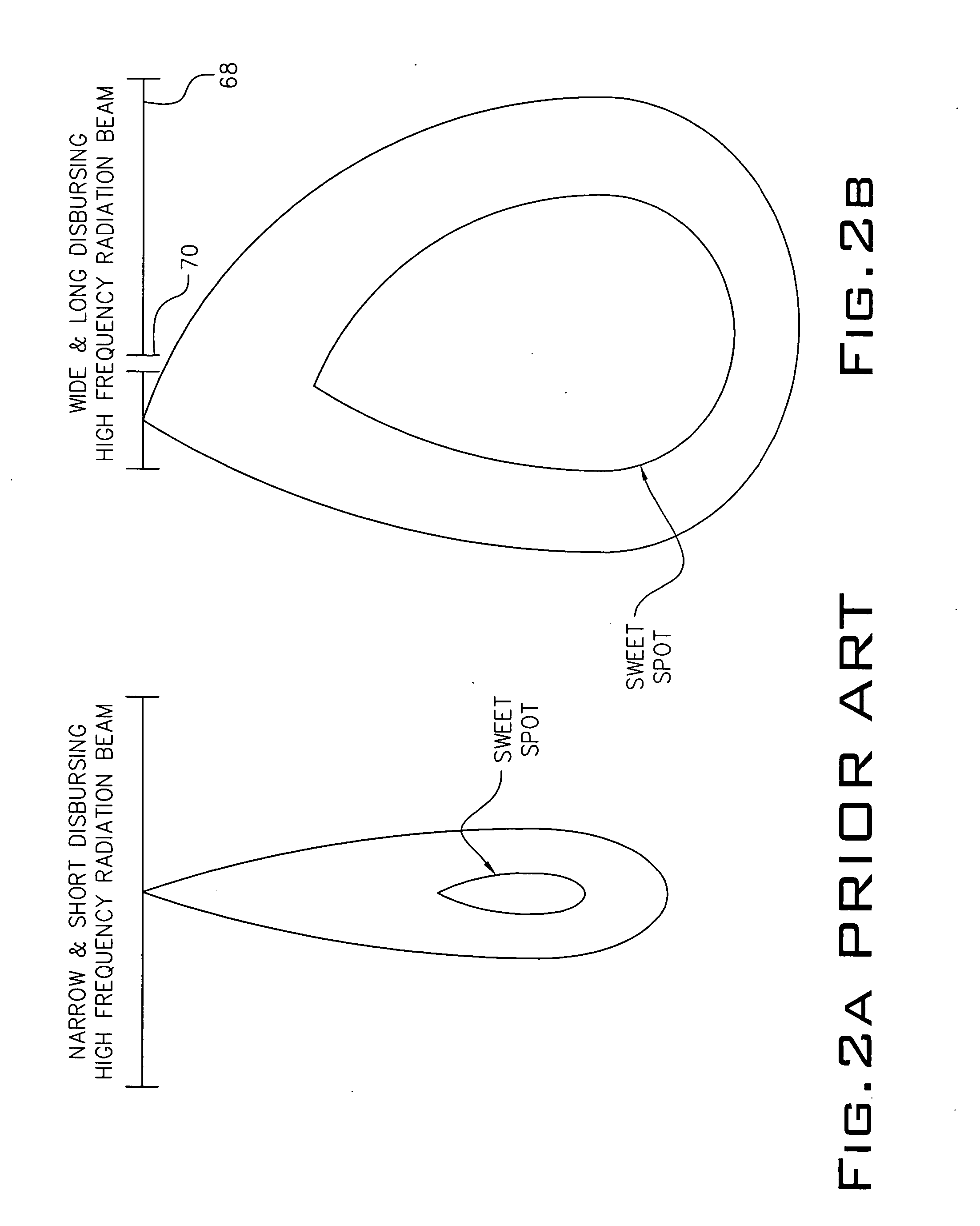
Prior art electrostatic speakers are also known to lack wide disbursement of the sound field they reproduce.
In particular, the mid and high frequencies are not very well spread in all directions due to being bundled on the speaker panel.
This is known as lacking in “directivity” or having a very narrow and short beam radiation.
However, this has added complexity and cost to known electrostatic speaker technology.

Method used


Image

  • Invertedly driven electrostatic speaker
  • Invertedly driven electrostatic speaker
  • Invertedly driven electrostatic speaker

Examples


Embodiment Construction

[0025] Referring to FIG. 1B, a novel electrical circuit 10 employed in an invertedly driven electrostatic speaker of the present invention is shown. An audio amplifier 12 provides an audio signal to be reproduced by a pair of invertedly driven electrostatic speakers of the present invention. Although not shown, it is understood that audio amplifier 12 is coupled to a audio player device, such as, for example, a CD player. The audio signal from audio amplifier 12 is applied at audio in 14 to a step-up transformer 16 since the audio signal outputted from audio amplifier 12 is at a signal level, which is insufficient to be reproduced by the speakers. In the preferred embodiment, a step-up transformer having a turn ratio of 1:100 is employed for producing a high voltage AC audio signal at audio out 18. This high voltage AC audio signal is applied to a thin film membrane (to be discussed in further detail herein below) of an electrostatic speaker of the present invention representing an ...


PUM


Abstract

An electrostatic speaker system is provided wherein a multitude of speakers are provided in the system, each speaker having a thin electrically conductive film membrane sandwiched between a pair of stator plates. The film membrane is directly coupled to a high voltage AC audio signal emanating from a power amplifier for reproducing an audio signal. The high voltage AC audio signal is not applied to the stator plates but instead indirectly coupled to the pair of stators by a plurality of condensers (in a voltage multiplier circuit) of a electrical circuit contained within each speaker of the system. By applying the high voltage AC audio signal to the film membrane, approximately one-quarter of the voltage typically used to drive an electrostatic speaker is required.

Description

BACKGROUND OF THE INVENTION [0001] 1. Field of the Invention [0002] The present invention relates to electrostatic speakers. More particularly, it relates to an electrostatic speaker invertedly driven with respect to traditional electrostatic speakers such that a high voltage AC audio signal is applied to the diaphragm and a static DC charge is applied to the stators. [0003] 2. Description of the Prior Art [0004] Electrostatic speakers utilize complex electrostatic circuitry to reproduce audio signals. Known electrostatic speakers reproduce sound by allowing a thin flexible diaphragm, having an electrical conductive surface applied thereto, to move between two fixed plates (front and rear), also known as the stators. Each stator is made to have the same area as the diaphragm. [0005] Prior art electrostatic speaker systems require a high voltage power supply to feed the diaphragm (also known as the membrane) with a permanent and unchanging (static) electrical charge typically between...

Claims


Application Information

Patent Timeline
IPC IPC(8): H04R19/02H04S3/00
CPCH04S3/002H04R19/02
Inventor SMITS, MAARTENDE HAAN, HIDDE W.
Owner TRANSPARENT SOUND TECH
Learn More