Eureka AIR delivers breakthrough ideas for toughest innovation challenges, trusted by R&D personnel around the world.

Device and method for determining a reproduction position

a technology of reproduction position and device, applied in the field of audio reproduction techniques, can solve the problems of significant audio quality decline, low spatial sound reproduction quality, and only rarely used wave-field synthesis in practice, and achieve the effects of low expenditure, improved accuracy, and reduced nois

Active Publication Date: 2005-07-07
FRAUNHOFER GESELLSCHAFT ZUR FOERDERUNG DER ANGEWANDTEN FORSCHUNG EV
View PDF5 Cites 99 Cited by
  • Summary
  • Abstract
  • Description
  • Claims
  • Application Information

AI Technical Summary

Benefits of technology

[0071] A further advantage of the present invention is the fact that only readily available input data will be required. With a view to recording, these are a sound-source position in the recording setting, a camera position in the recording setting and an aperture angle of the camera. With a view to the reproduction circumstances, these are the width of a reproduction screen as well as, optionally, an aperture angle of a reproduction device, the aperture angle normally being predefined by the given technical facts of a reproduction device, the width of a reproduction surface and the distance between the reproduction surface and the reproduction source.
[0072] In accordance with the invention, exact positioning of sources of sound is thus achieved in a reproduction environment to adjust a reproduction scene to differing recording situations.
[0073] Eventually, the present invention is advantageous in that due to the two different cases which lead to a differentiation of a total of four cases, the sound-source positioning is transparent, flexible, low in expenditure, and, in particular with regard to taking into account various accuracy requirements, scalable.
[0074] There are various possibilities of how to deal with the interfaces with the screen or the projection sphere. For a calculation which is simple and may thus be performed at lower expenditure, the source of sound may be placed on the screen, or the projection sphere, without taking into account the length of the sound-source vector, in the case of the standard aperture angle. In the event of a deviating aperture angle, the distance and the difference may be calculated on the basis of this value.
[0075] For a calculation which is more accurate but requires a increased expenditure, the length of the sound-source vector is taken into account in the recording setting so as to place the source of sound before, or behind, the screen or projection sphere, even with an existing standard aperture angle of the camera, by scaling the vector to the point of intersection with the screen or sphere, to make its length identical with the sound-source vector from the camera setting. If the aperture angle of the camera deviates from the standard aperture angle, the reproduction position of the source of sound is shifted by the difference, starting from a position located before or behind the screen or sphere.
[0076] To enlarge the optimum viewpoint, the placement of the source of sound before or behind the screen, and / or the shifting of the source of sound may be performed in a nonlinear manner due to a zoom / wide-angle positioning, it being possible to also use thresholds in that shifting of the source of sound to before or behind the screen or projection sphere is admitted only up to a selectable maximum amount.

Problems solved by technology

In previous audio systems, a substantial disadvantage has been the quality of the spatial sound reproduction of natural, but also of virtual environments.
All common techniques have the disadvantage that both the site of the loudspeakers and the position of the listener are already impressed on the transfer format.
With incorrect arrangement of the loudspeakers with reference to the listener, audio quality suffers significantly.
Due to this method's enormous requirements for computer power and transfer rates, wave-field synthesis has up to now only rarely been employed in practice.
Although wave-field synthesis functions well for environments whose conditions are known, irregularities occur if the conditions change or if wave-field synthesis is executed on the basis of an environmental condition which does not match the actual condition of the environment.
The acoustic impression matching the image is usually subsequently impressed on the audio signal by manual steps during so-called post-production, or is classified as too expensive and time-consuming in its implementation, and is thus neglected.
Thereby, usually a contradiction of the individual sensual perceptions arises, which leads to the designed space, i.e. the designed scene, being perceived as less authentic.

Method used


Image

  • Device and method for determining a reproduction position
  • Device and method for determining a reproduction position
  • Device and method for determining a reproduction position

Examples


Embodiment Construction

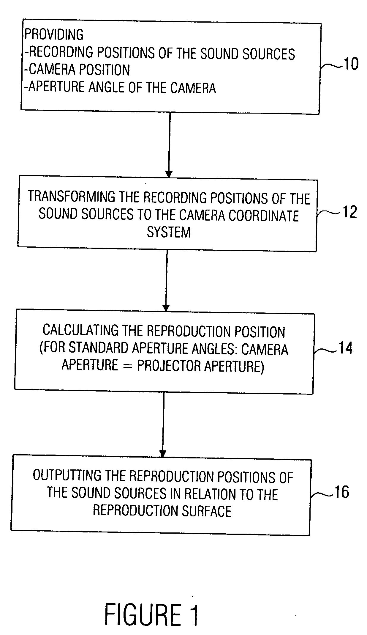
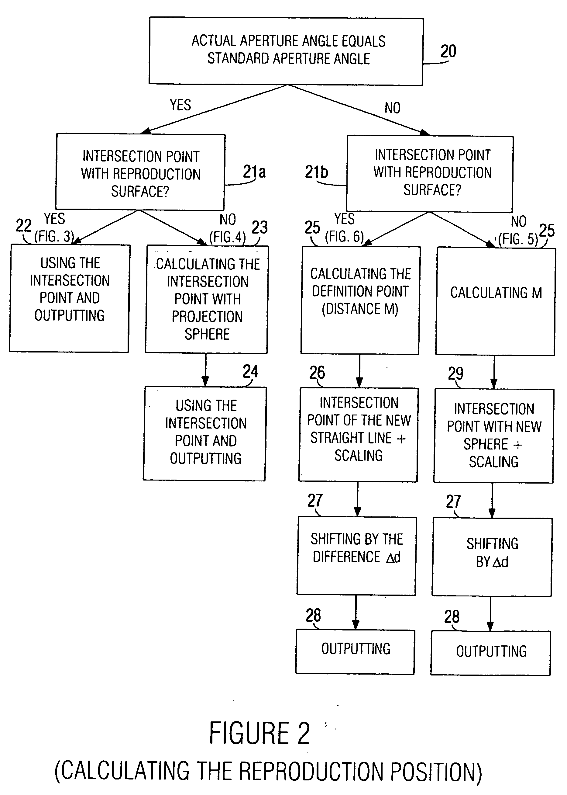
[0086]FIG. 1 shows an overview block diagram of the inventive device for determining a reproduction position, FIG. 2 showing a more detailed representation of the means for calculating the reproduction position of FIG. 1.

[0087] In particular, the inventive device shown in FIG. 1 and / or the inventive method diagrammatically depicted in FIG. 1 serve to determine a reproduction position of a source of sound for an audio-visual reproduction of a film scene from a plurality of individual pictures or frames with regard to a reproduction surface having a predetermined width, and with regard to a projection source having a projection reference point. The reproduction surface may be, for example, a screen in a cinema. The width of the screen will vary from cinema to cinema. At any rate, however, it is predetermined, i.e. specified by the cinema in question. The projection source may be a cinema film projector, as is usually employed in cinemas or other facilities. Alternatively, the project...


PUM


Abstract

A device for determining a reproduction position of a source of sound for audio-visual reproduction of a film scene from a plurality of individual pictures with regard to a reproduction surface having a predetermined width and a projection source having a projection reference point comprises means for providing a recording position of the source of sound, a camera position during recording, and an aperture angle of the camera during recording. In addition, provision is made of means for transforming the recording position of the source of sound to a camera coordinate system, the origin of which is defined, in relation to a camera aperture, to obtain a recording position of the source of sound in the camera coordinate system. Means for calculating the reproduction position of the source of sound in relation to the projection reference point determines whether the aperture angle of the camera equals a predetermined aperture angle, and whether or not a source of sound is located within the visual range of the camera. If the current aperture angle of the camera differs from the predetermined standard aperture angle, the reproduction position of the source of sound is spaced toward a viewer, or away from the viewer, by a distance which depends on the ratio of the standard aperture angle to the current aperture angle. Hereby, automatable sound-source positioning is achieved so as to provide not only a visually realistic, but also an acoustically realistic situation in a reproduction room using wave-field synthesis methods.

Description

CROSS-REFERENCE TO RELATED APPLICATION [0001] This is a continuing application, under 35 U.S.C. § 120, of copending international application No. PCT / EP2004 / 000463, filed Jan. 21, 2004, which designated the United States; this application also claims the priority, under 35 U.S.C. § 119, of German patent application No. 103 05 820.6, filed Feb. 12, 2003; the prior applications are herewith incorporated by reference in their entirety.BACKGROUND OF THE INVENTION 1. Field of the Invention [0002] The present invention relates to audio reproduction techniques and, in particular, to audio reproduction techniques which are suitable for wave-field synthesis modules to conduct a source of sound positioning tuned to a video reproduction. [0003] 2. Description of Prior Art [0004] There is an increasing need for new technologies and innovative products in the area of consumer electronics. It is an important prerequisite for the success of new multimedia systems to offer optimal functionalities o...

Claims


Application Information

Patent Timeline
Patent Type & Authority Applications(United States)
IPC IPC(8): H04N7/24H04N7/52H04S3/00
CPCH04N5/2224H04N21/235H04N21/2368H04N21/4341H04S2420/13H04N21/8106H04N21/8547H04S3/002H04N21/435
Inventor MELCHIOR, FRANKBRIX, SANDRA
Owner FRAUNHOFER GESELLSCHAFT ZUR FOERDERUNG DER ANGEWANDTEN FORSCHUNG EV
Why Eureka
Eureka Blog
Learn More