Decoding device, electronic apparatus, computer, decoding method, program, and recording medium

a decoding device and electronic equipment technology, applied in signal generators with optical-mechanical scanning, color television with bandwidth reduction, etc., can solve the problem of large amount of computation required for decoding image data encoded using such technologies, and achieve the effect of reducing the time required for decoding image data that requires referencing another image during the decoding time and significantly reducing the amount of computation required for each process

Inactive Publication Date: 2005-07-07
SONY CORP
View PDF1 Cites 20 Cited by
  • Summary
  • Abstract
  • Description
  • Claims
  • Application Information

AI Technical Summary

Benefits of technology

[0023] Accordingly, it is an object of the present invention to provide a technology for decoding an image stream including inter-frame predictive-coded image data at high speed.
[0029] In a group of frames, which is a unit of access, the combination between the various types of frames may be freely determined. Here, the group of frames is defined as a series of frames between one intra-coded frame and next intra-coded frame. Additionally, the number of bi-directionally predictive-coded frames in the group of frames may be freely determined. In general, as the number of bi-directionally predictive-coded frames decreases, the image quality increases.
[0034] As a result, a decoding time of the decoding device can be decreased. Additionally, each decoding unit requires much lower processing power compared to a decoding unit executing all required computations. This results in decrease in development cost and product cost compared to a use of one high-performance decoding unit.
[0051] According to the aspect of the present invention, application software functions as the above-described decoding unit. The processing units 51 and 52 correspond to the decoding units. Thus, the decoding process of an image stream may be distributed to a plurality of processing units (processors). This configuration decreases processing power required for each processing unit.
[0054] As described above, according to the present invention, a decoding process of image data that requires referencing another image during a decoding time is distributed. Thus, a computational amount required for each process can be significantly reduced. As a result, a time required for decoding image data that requires referencing another image during the decoding time can be decreased.

Problems solved by technology

Decoding image data encoded using such technologies require a large amount of computations.

Method used


Image

  • Decoding device, electronic apparatus, computer, decoding method, program, and recording medium
  • Decoding device, electronic apparatus, computer, decoding method, program, and recording medium
  • Decoding device, electronic apparatus, computer, decoding method, program, and recording medium

Examples


embodiment

(4) Effect of Embodiment

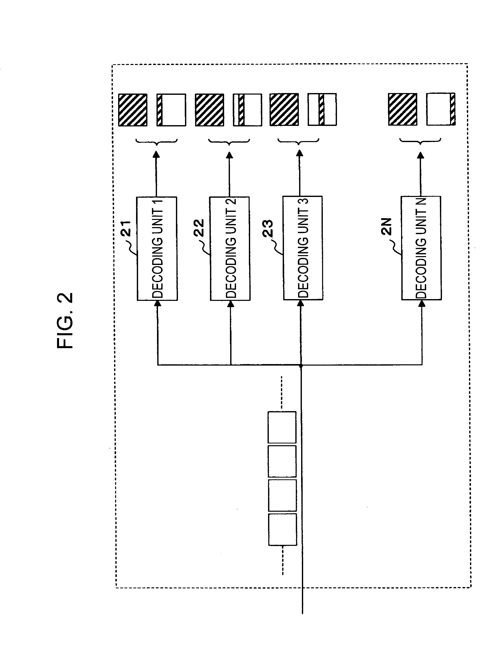
[0095] As described above, the decoding process of a B frame that requires a huge amount of computation is carried out by parallel processes of “N” number of the sub-decoders 142, each of which requires only one Nth of the amount of computation. As a result, a decoding time of the MPEG decoder 140 is significantly reduced.

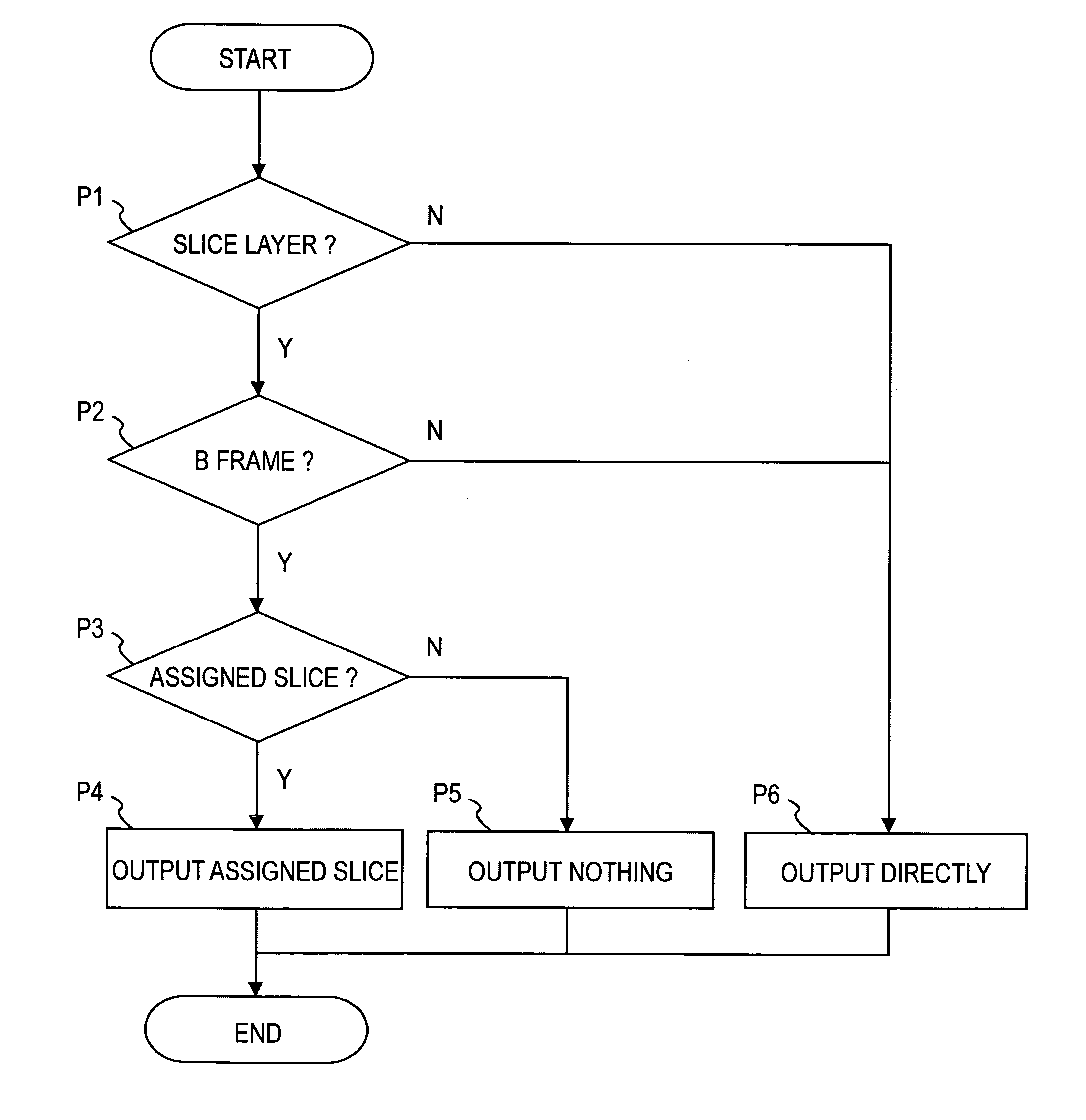
[0096] Furthermore, since each of the sub-decoders 142 outputs a slice corresponding to the decoded slice of a B frame, the sub-decoder 142 carries out the same operations regardless of the type of a frame to be decoded. That is, the sub-decoder 142 needs not to determine the type of a frame at output time. This configuration can simplify the output process.

(5) Other Embodiments

[0097] While a stored system is described in the above-described embodiments, the present invention can be applied to a broadcasting system. That is, the present invention can be applied to a decoding unit that decodes an MPEG stream received over the radio or a n...


PUM


Abstract

A decoding device for decoding an image stream containing bi-directionally predictive-coded image data includes “N” number of decoding units for decoding the image stream in a parallel manner, wherein “N” is a natural number greater than or equal to 2. Each of the decoding units decodes a partial image being assigned to the decoding unit out of “N” number of partial images forming a frame when the bi-directionally predictive-coded image data is input, and decodes an entire frame when image data coded by using a method other than the bi-directionally predictive-coding method is input.

Description

BACKGROUND OF THE INVENTION [0001] 1. Field of the Invention [0002] The present invention relates to a decoding device for decoding an image stream containing predictive-coded image data between frames. The present invention also relates to an electronic apparatus including the decoding device. The present invention also relates to a computer for executing the function of the decoding device. The present invention also relates to a method and a program for decoding an image stream containing predictive-coded image data. Finally, the present invention relates to a recording medium for recording the program. [0003] 2. Description of the Related Art [0004] Recently, a variety of image compression technologies has been proposed. For example, H.261 and MPEG (Motion Picture coding Experts Group) standards are proposed. Decoding image data encoded using such technologies require a large amount of computations. [0005] Therefore, in general, a specialized hardware accelerator (LSI) is used i...

Claims


Application Information

Patent Timeline
Patent Type & Authority Applications(United States)
IPC IPC(8): H04N19/50H04N19/102H04N19/159H04N19/172H04N19/176H04N19/189H04N19/436H04N19/44H04N19/503H04N19/577H04N19/80
CPCH04N19/159H04N19/172H04N19/61H04N19/436H04N19/44H04N19/423H04N19/174H04N19/577
Inventor SHIBATA, SHOJIROKOBAYASHI, MITSUGU
Owner SONY CORP
Why Eureka
Try Eureka