
Using organic light emitting diodes (OLEDs) in landscape lighting applications

a technology of organic light and diodes, applied in the field of low-voltage solar technology platforms for landscape lighting applications, can solve the problems of low efficiency, large size and increased weight, low cost of electronic transformers, etc., and achieve the effects of low cost, low input power, and high light outpu

Inactive Publication Date: 2005-07-07
GENERAL ELECTRIC CO
View PDF2 Cites 44 Cited by
  • Summary
  • Abstract
  • Description
  • Claims
  • Application Information

AI Technical Summary

Benefits of technology

[0013] Clearly, an OLED light source provides for low cost, low input power, high light output, high spectral efficiency, and an increased life, while also permitting the OLED to be conformed to various shapes and provide different color options.

Problems solved by technology

Thus, although an electromagnetic transformer is low cost, it has low efficiency, large size and increased weight.
The electronic transformer, on the other hand, has a high cost, a medium efficiency, and a reduced size and weight.
Last, the AC-DC converter is approximately medium cost with a high efficiency, but is of medium size and weight.
When driving an LED light source, though, the DC-type drive circuit has a low spectral efficiency and only a medium LED life.
A pulse width modulated system, on the other hand, has a high cost and low efficiency, even though it results in high spectral efficiency and increased LED life.
Although halogen / incandescent light sources are low cost, they require high input power providing a high range of light output, and have a low spectral efficiency and low life expectancy.
LEDs, on the other hand, are of medium cost and require a low input power.
Even though LEDs have an extended life, the light output is low and the spectral efficiency is only rated at a medium level.
Fluorescent light sources have a high cost associated therewith, and a medium range of input power resulting in high light output, high spectral efficiency, but only a medium life.
In addition, fluorescent light sources often require complex drive circuit (ball) and perform poorly at low temperatures.

Method used


Image

  • Using organic light emitting diodes (OLEDs) in landscape lighting applications
  • Using organic light emitting diodes (OLEDs) in landscape lighting applications

Examples


Embodiment Construction

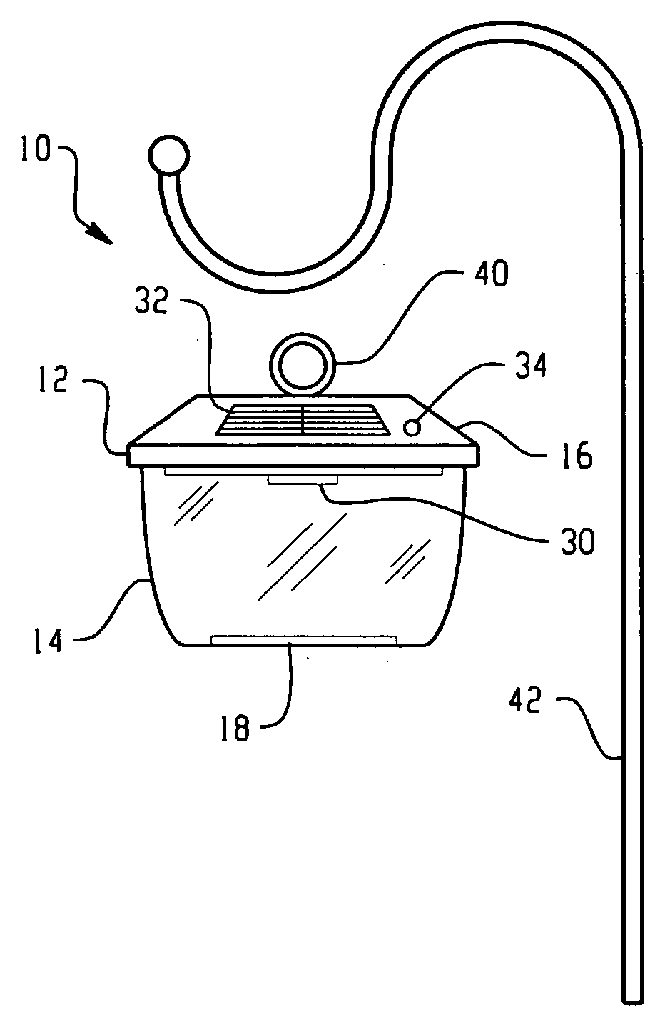
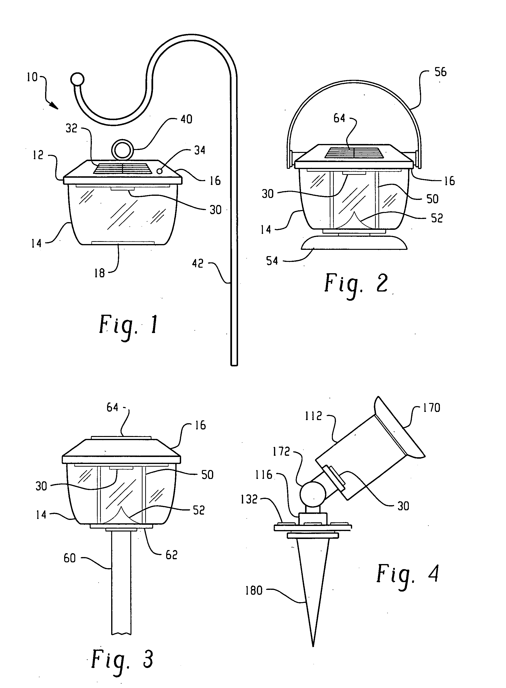
[0019]FIG. 1 illustrates a light assembly 10 particularly used for area landscape lighting. A housing 12 includes a light transmissive or clear lens portion 14 and a circuit housing portion 16. Typically, the light transmissive portion is a hollow chamber formed of a transparent plastic or similar material and may include a diffuser 18. Here, the diffuser 18 is disposed along a lower planar surface of the housing so that light emanating from the light source is generally evenly spread over the ground surface. The light source 30 is an organic light emitting diode (OLED). The OLED is preferably located at the other end of the transparent housing portion, particularly, the OLED is secured to a lower surface or underside of the circuit housing.

[0020] A power source is housed within the housing and is preferably an electronic transformer that receives electrical energy from a photovoltaic panel 32. One or more panels may be provided on an upper surface of the circuit housing portion wh...


PUM


Abstract

A landscape lighting assembly and directional lighting arrangement uses an organic light emitting diode (OLED) light source. The low cost and low power required to operate the OLEDs offer many features and benefits over prior arrangements. In addition, it provides high light output and desired spectral efficiencies, along with an extended life.

Description

FIELD OF THE INVENTION [0001] This invention relates to a lighting assembly, and more particularly to low voltage solar technology platforms for lighting applications. BACKGROUND OF THE INVENTION [0002] Presently, landscape lighting systems, and backlighting systems for signage, fall into one of two technology platforms. The first type is a low voltage system which includes a central step-down transformer unit that converts standard 120 VAC, 60 Hz power line input into a 12 volt signal. The transformer powers a series of lamp nodes that are wired in parallel to a central supply wire. The supply wire is typically buried in the ground. In some instances, a standard electromagnetic transformer merely steps the input voltage down while maintaining the same frequency. Other low voltage systems use an electronic transformer that not only steps the input voltage down to the desired 12 VAC operating range, but significantly increases the frequency (e.g., 50 KHz). Still other systems use an ...

Claims


Application Information

Patent Timeline
Patent Type & Authority Applications(United States)
IPC IPC(8): H01L51/50F21S8/00F21S8/08F21S9/02F21S9/03F21V23/00F21Y105/00
CPCF21S8/081F21S9/03F21V21/0824Y02B20/36F21Y2101/02F21Y2105/008F21W2131/10F21Y2105/00F21Y2115/15Y02B20/30Y02B20/72
Inventor CECH, LEONARDTREVINO, BENIT
Owner GENERAL ELECTRIC CO
Learn More