
Programmable power supply having digitally implemented slew rate controller

a technology of slew rate controller and power supply, which is applied in the direction of power conversion systems, dc-dc conversion, instruments, etc., can solve the problems of increasing test costs, requiring more complicated tests, and the practical limit of instantaneous power and current for typical power supplies, so as to achieve the effect of scaling the slop

Inactive Publication Date: 2005-07-07
AGILENT TECH INC
View PDF1 Cites 40 Cited by
  • Summary
  • Abstract
  • Description
  • Claims
  • Application Information

AI Technical Summary

Benefits of technology

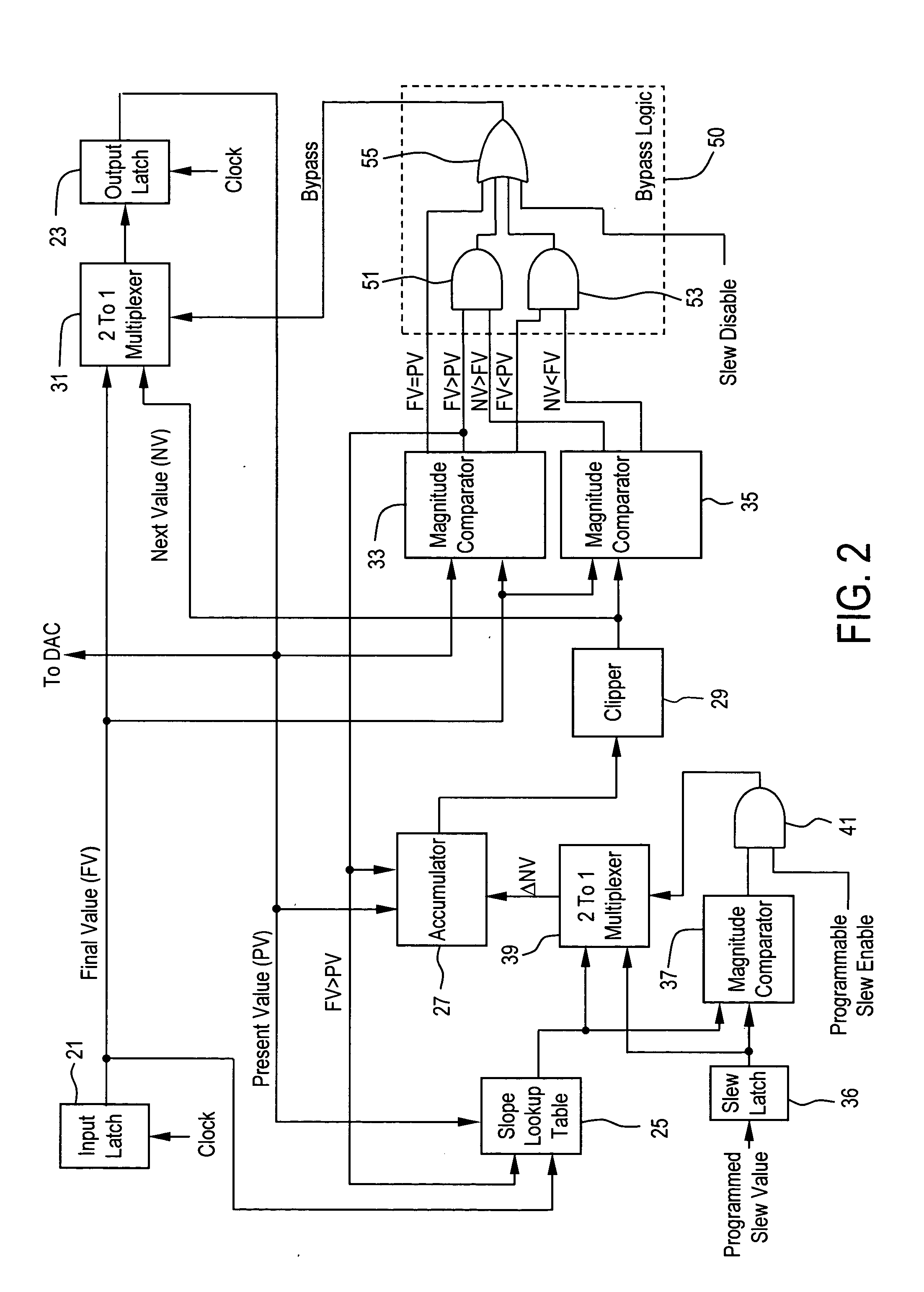
[0026] A further advantage of the present invention is realized for applications that are sensitive to the maximum rate of change of the power supply output. In these cases, the look-up table may be modified to allow the slope of the output to be controlled at slower rates than the maximum for optimum transitions. By making the table RAM based, user access can be provided to allow unique transition characteristics to be created to meet the complex needs of end users, without any hardware changes being required. These changes can be generated at digital logic speeds.
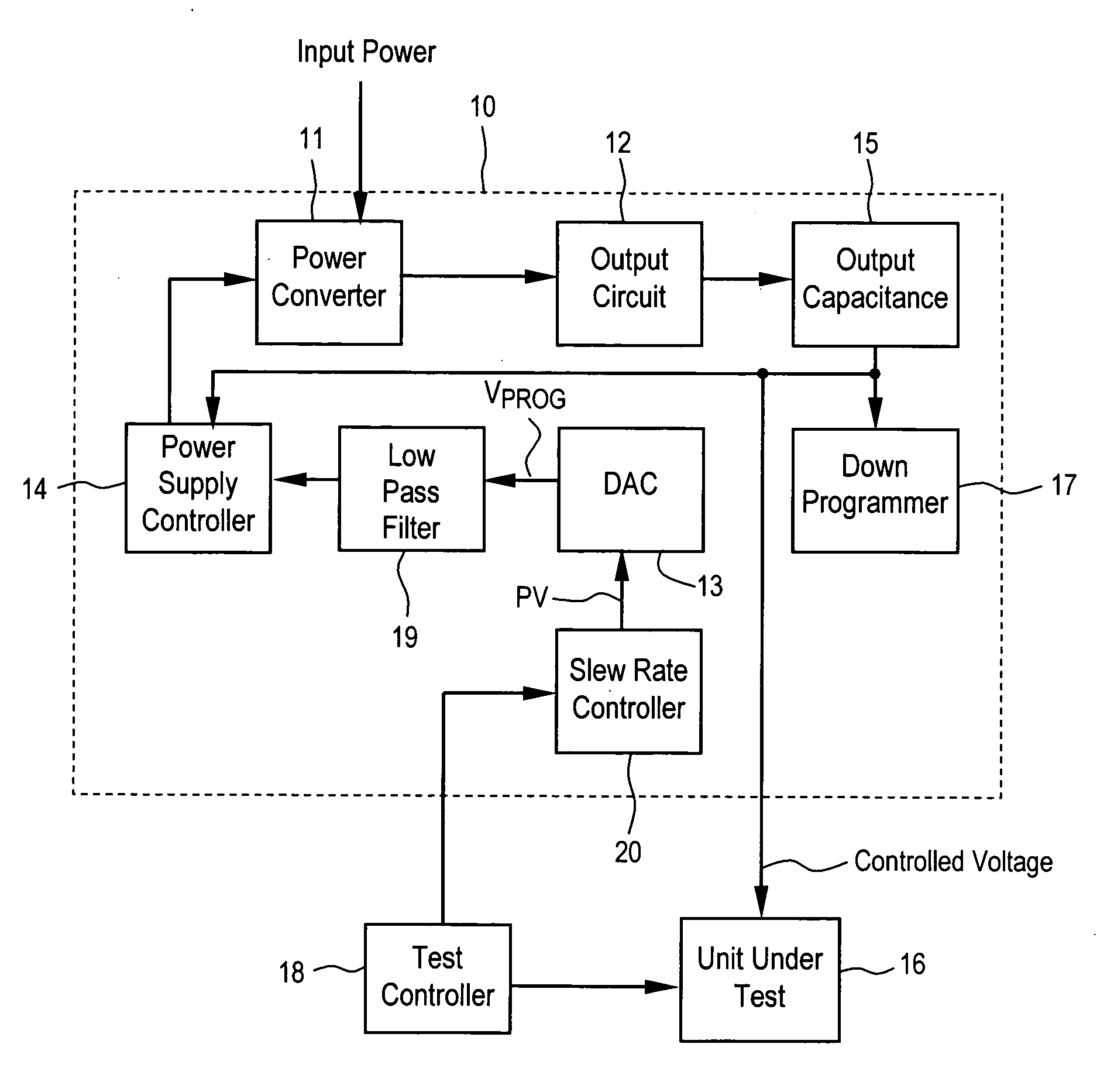
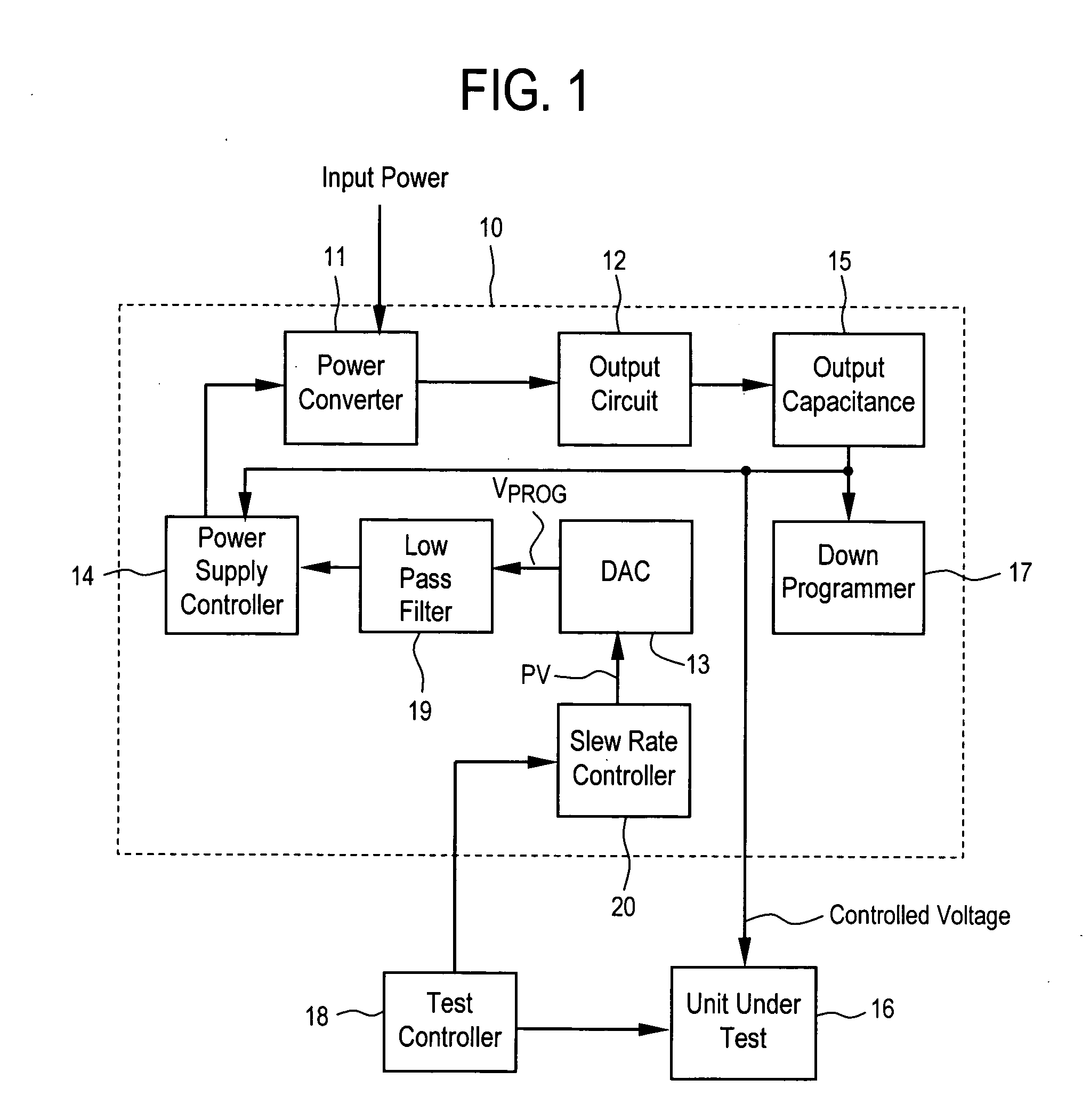
[0027] Control of maximum slew rate is provided by limiting or “clipping” the maximum offset added to the DAC on each step. Additional segments of the table may be engaged when the power supply is switched to different ranges, effectively scaling the slope to compensate for different gains from the programming port to the output. The table is corrected to compensate for any inherent slew limiting in the voltage control subsystem, correcting for and further limiting the output transitions in view of a non-ideal voltage loop bandwidth.

Problems solved by technology

Cost of test is increasing as products become more sophisticated, requiring more complicated tests.
A typical power supply has a practical limit of an amount of instantaneous power and current that the power supply can deliver to the load.
If the limiting current capacity is exceeded by trying to force the power supply to change faster than the combined charging current of the output capacitor and the load current, the power supply will cease to be regulated by feedback systems, resulting in an occurrence of overshoots or undershoots and causing test errors in a production test system.
Many loads are extremely sensitive to excessive voltage excursions, causing testing errors and possible device damage.
If the protection circuits engage during normal output transitions, the protection circuits may cause overshoots or undershoots in the output when the protection circuits disengage.
Although slew rate control circuits are relatively easy to implement, known implementations do not provide a optimum rate of change at all operating points.
While the dual rate RC low pass filter circuit has superior output speed compared with the single stage RC low pass filter circuit, the dual rate RC low pass filter circuit is substantially more complex and costly, since the parts used are in the programming path and must be high precision to control accuracy of the voltage programming system.
The overshoot control circuits are difficult to design for proper operation without causing instabilities and minimal overshoots over a wide set of output voltage and current operating points.

Method used


Image

  • Programmable power supply having digitally implemented slew rate controller
  • Programmable power supply having digitally implemented slew rate controller
  • Programmable power supply having digitally implemented slew rate controller

Examples


Embodiment Construction

[0028] The present invention will become more apparent and more readily appreciated from the following description of the various embodiments, taken in conjunction with the accompanying drawings in which:

[0029]FIG. 1 is a block diagram of an embodiment of a power supply of the present invention;

[0030]FIG. 2 is a block diagram of the slew rate controller shown in FIG. 1;

[0031]FIG. 3 is a graphic representation of a power curve used for calculating slew rates of the power supply shown in FIG. 1;

[0032]FIG. 4 is an equation defining a voltage that describes the output voltage when the starting and finishing voltages are both below the lower knee voltage, VLK, shown in FIG. 3;

[0033]FIG. 5 is an equation defining a voltage that describes the output voltage when the present voltage is below the lower knee voltage, VLK, shown in FIG. 3, and the final voltage, VF, is greater than the lower knee voltage, VLK shown in FIG. 3;

[0034]FIG. 6 is an equation defining a voltage that describes t...


PUM


Abstract

A digitally implemented slew rate controller for a power supply and a power supply having the same. An output up-programming signal is provided that enables the power supply to change an output voltage and current at a maximum rate which does not engage the protection circuits which are employed to protect components of the power supply. The maximum rate of change decreases as the output voltage increases. The up-programming speed of the power supply output optimizes the output by considering that an amount of output current available for charging an output capacitor of the power supply will decrease as the output voltage increases for a resistive load. An output down-programming control signal enables a discharge device to dissipate heat with a constant power characteristic, which will minimize a time required to reduce the output voltage while not exceeding a maximum power dissipation rating of the discharge device.

Description

CROSS-REFERENCE TO RELATED APPLICATIONS [0001] Not Applicable BACKGROUND OF THE INVENTION [0002] 1. Field of the Invention [0003] The present invention relates to a power supply having a digitally implemented slew rate controller, and more particularly to a power supply having a digitally implemented slew rate controller which optimizes up and down programming speed in programmable power supplies while minimizing overshoots. [0004] 2. Description of the Related Art [0005] Power supplies are a useful tool for performing system tests of electronic devices during manufacture of the devices and test system throughput is a critical factor in controlling manufacturing overhead. Cost of test is increasing as products become more sophisticated, requiring more complicated tests. Power supplies are a part of a minimum set of test apparatus connected during any system test and are a significant part of total system throughput. [0006] System power supplies are required to change output state qu...

Claims


Application Information

Patent Timeline
Patent Type & Authority Applications(United States)
IPC IPC(8): G05F1/40G05F1/46
CPCH02M2001/0029H02M3/157H02M1/0029
Inventor KENNY, JOHNBENES, MICHAEL JOSEPHVULOVIC, MARKO
Owner AGILENT TECH INC
Learn More