
Water circulation systems for ponds, lakes, and other bodies of water

a technology for ponds and lakes, applied in the direction of positive displacement liquid engines, piston pumps, liquid fuel engines, etc., can solve the problems of high flow circulation patterns throughout the entire body of water discussed above, ineffective waste processing, and ineffective waste processing, etc., to achieve less turbulence and increase the flow rate

Active Publication Date: 2005-06-30
IXOM OPERATIONS
View PDF14 Cites 15 Cited by
  • Summary
  • Abstract
  • Description
  • Claims
  • Application Information

AI Technical Summary

Benefits of technology

[0011] In operation, water from the depths of the pond is uplifted by the impeller through the draft tube toward the housing and dish. In doing so and in the preferred manner of use, the uplifted water passes out not only up over the upper edge of the dish but also out the annular opening between the housing and the dish. Preferably, about ⅔rds of the volume of the uplifted water passes out the annular opening and ⅓rd continues upwardly into and out of the dish. With this design, a significantly higher flow rate can be handled by the system without creating undesirable turbulent flow at the surface of the pond or other body of water.
[0012] The impeller preferably includes two, half blades with diameters less than the diameters of the housing and the bottom of the dish. In this manner, a gap is created between the blades and the housing as well as the dish which generates less turbulence in the uplifted water. The smaller diameters also permit the vertical positioning of the impeller blades relative to the dish and housing to be adjusted. This adjustment in turn allows the proportions of the uplifted water discharged through the annular opening and over the top of the dish to be varied as desired.
[0013] The draft tube is specially constructed to have a neutral or slightly positive buoyancy and a cable arrangement is provided to selectively adjust the extended length and depth of the collapsible tube. The cable arrangement includes a spring to aid in protecting the main cable and tube from damage from the uplifting forces of surface waves on the flotation platform. Additionally, the arrangement includes a short length of cable positioned adjacent the spring which limits the maximum extension of the spring and overall cable arrangement to protect the draft tube from being stretched beyond its design limits. An electronic eutrophication control system can also included to create apatite from calcium and phosphate molecules present in the water.
[0015] Still other embodiments include a connecting arrangement between the drive motor and the impeller that permits the two to be easily and quickly coupled and uncoupled. The connecting arrangement also is designed to accommodate slight misalignments between the drive shaft of the motor and the driven shaft of the impeller. An arrangement to adjust and calibrate the depth of the inlet to the draft tube is disclosed. Solar panels are also provided which can be pivotally swung outwardly to open positions to provide better visibility and access to the interior of the flotation platform and the components on it including the impeller. The solar panels are additionally mounted via slotted tracks for movement about a horizontal axis and a modified panel is disclosed that faces toward the central axis of the flotation platform rather than away from it. Arrangements are further provided wherein the operation of the system can be monitored and controlled including remotely from shore or a central location.

Problems solved by technology

Power availability to run the pump or impeller of the circulation system and seasonal weather conditions (e.g., surface ice) present great design challenges for optimum performance.
Remote ponds or other bodies of water can be a particular challenge as the only available power source may be solar energy.
In circulation systems for smaller bodies of water such as municipal wastewater ponds for treating domestic and industrial wastes, the high flow circulation pattern throughout the entire body of water discussed above is not always effective to process the wastes and in some cases can be counterproductive.
One problem in such smaller ponds (e.g., 5 to 15 feet deep) is that the domestic and commercial wastes are usually much stronger and more concentrated.
Also, such municipal wastewater ponds rely on more complicated mechanisms including biological and chemical ones for treating and processing the waste.
Each zone is essential for the proper and overall treatment and processing of the various and different waste materials and each zone has its own biological and chemical needs that are often the opposite of the other and often detrimental to the other.
Consequently, any thorough and overall mixing of the entire pond as in the earlier high flow systems for larger bodies of water will normally destroy the two zones and the effectiveness of the wastewater treatment pond.

Method used


Image

  • Water circulation systems for ponds, lakes, and other bodies of water
  • Water circulation systems for ponds, lakes, and other bodies of water
  • Water circulation systems for ponds, lakes, and other bodies of water

Examples


Embodiment Construction

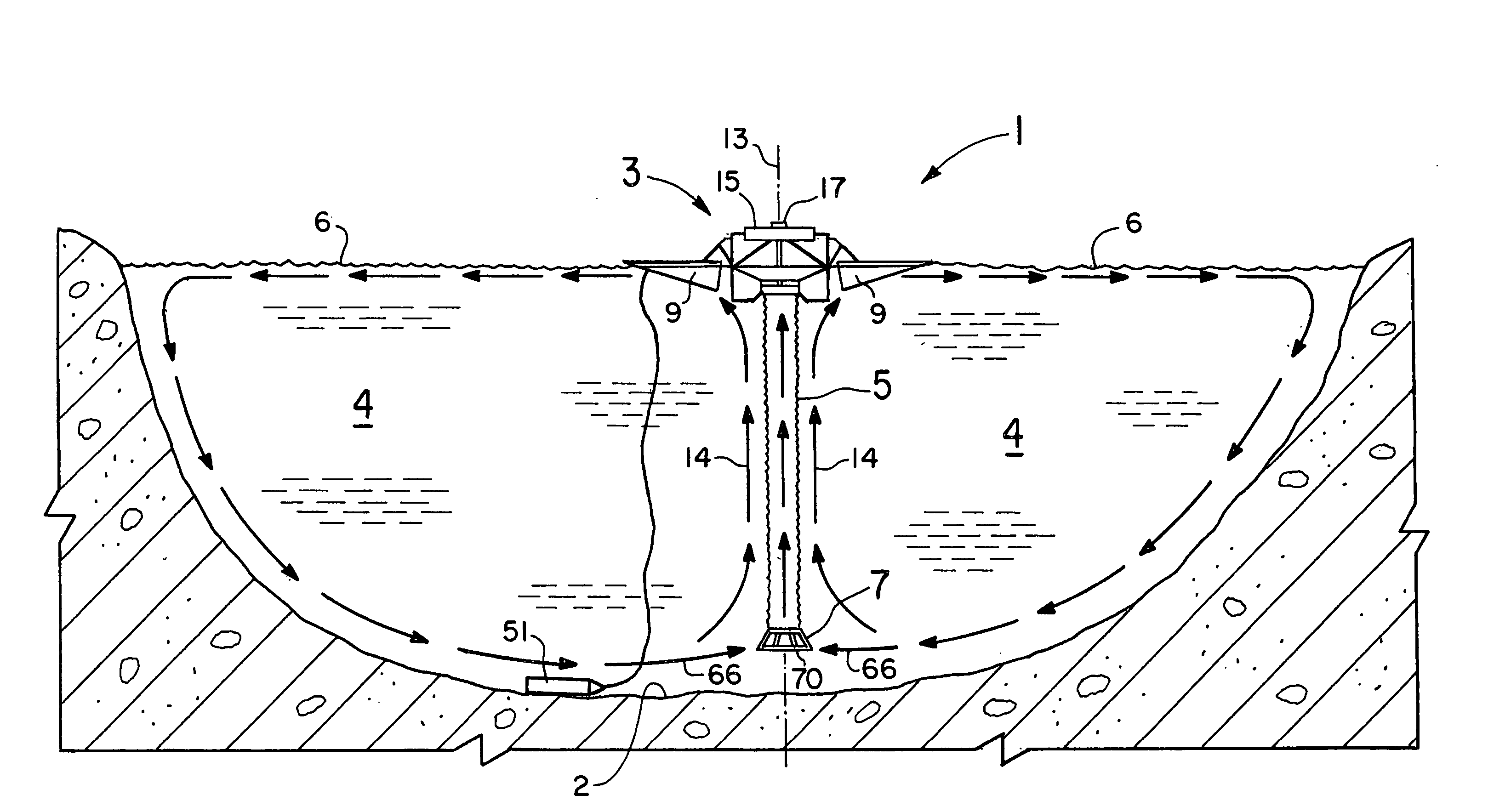
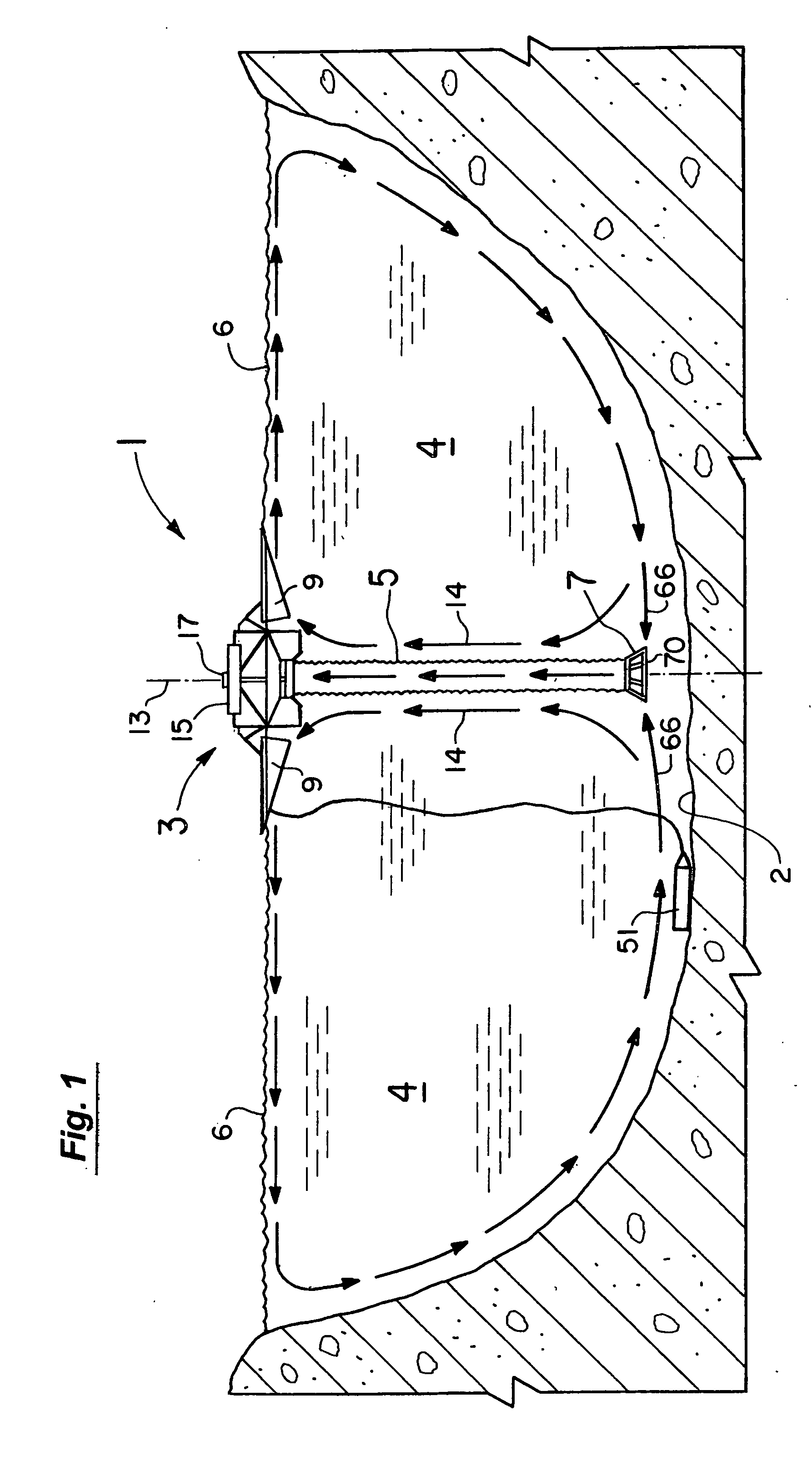
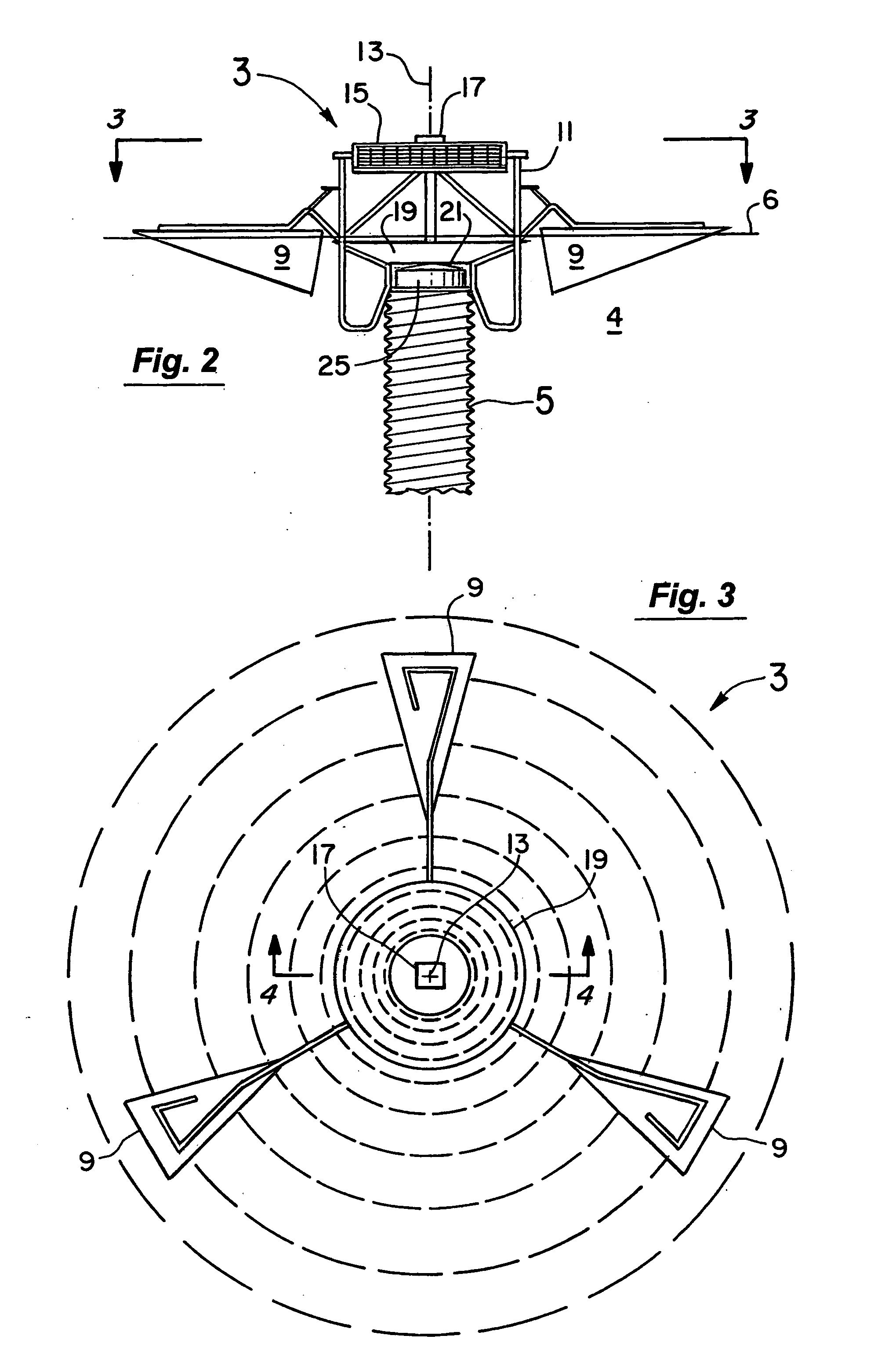
[0050] As schematically shown in FIG. 1, the water circulation system 1 of a first set of embodiments of the present invention includes an upper flotation platform 3 with a draft hose or tube 5 depending downwardly from it to the water inlet 7. The inlet 7 is preferably positioned adjacent and slightly raised from the bottom 2 of the pond or other body of water 4. The flotation platform 3 as best seen in FIGS. 2 and 3 includes three floats 9 supported on the tubular frame 11 of the platform. The floats 9 extend outwardly of the central axis 13 and are preferably evenly spaced about the axis 13 (see FIG. 3). The floats 9 extend far enough out from the central axis 13 to provide a relative stable and buoyant support structure for the system 1 including its solar panels 15, electric motor 17, dish 19 (see also FIGS. 4 and 5), impeller 21 (see also FIGS. 4 and 6), draft hose 5, and the water inlet 7 of FIG. 1. As explained in more detail below, the draft hose 5 is also specially designe...


PUM

PropertyMeasurementUnit
diameteraaaaaaaaaa
diameteraaaaaaaaaa
diameteraaaaaaaaaa

Abstract

Circulation systems for ponds, lakes, or other bodies of water using a flotation platform, dish, and impeller. One embodiment has a connecting arrangement between the drive motor and the impeller that permits the two to be easily and quickly coupled and uncoupled. The connecting arrangement also is designed to accommodate slight misalignments between the shafts. An arrangement to adjust and calibrate the depth of the inlet to the draft tube is disclosed. The system further includes solar panels that can be pivotally swung outwardly to open positions, angularly adjusted about a horizontal axis, and mounted to face toward the central axis of the flotation platform rather than away from it. Arrangements are further provided to monitor and control the components of the system including remotely from shore.

Description

RELATED APPLICATIONS [0001] This application is a continuation-in-part of U.S. patent application Ser. No. 10 / 749,064 filed Dec. 30, 2003, which claims the benefit of U.S. Provisional Patent Application Ser. No. 60 / 437,217 filed Dec. 31, 2002, both of which applications are incorporated herein by reference.BACKGROUND OF THE INVENTION [0002] 1. Field of the Invention [0003] This invention relates to the field of circulation systems for ponds, lakes and other bodies of water and more particularly to the field of such circulation systems for relatively large and deep bodies of water that require fairly high flow rates to be most effective and systems for smaller bodies such as municipal wastewater ponds that are designed primarily for treating domestic and industrial wastes and have special requirements to be effective. [0004] 2. Discussion of the Background [0005] In regard to larger and deeper bodies of water that require high flow rates to be most effective, the fundamental goal of ...

Claims


Application Information

Patent Timeline
Patent Type & Authority Applications(United States)
IPC IPC(8): B01F3/04B01F13/00C02F3/16C02F7/00
CPCB01F3/04609B01F13/0049C02F3/16C02F7/00B01F7/00725C02F2209/22C02F2209/40F04D13/066C02F2201/009Y02W10/37Y02A20/212Y02W10/10B01F23/23341B01F27/213B01F33/503
Inventor TORMASCHY, WILLARD R.KUDMA, GARY A.OBRITSCH, TAIT J.BLETH, JOEL J.SIMNIONIW, COREY M.
Owner IXOM OPERATIONS
Learn More