Screw-in valve
a screw-in valve and valve body technology, applied in the direction of valve housing, valve operating means/release devices, transportation and packaging, etc., can solve the problem that the assembly of the screw-in valve can even be carried out by untrained personnel under time pressure, and achieve the effect of preventing the movement of the valve piston
- Summary
- Abstract
- Description
- Claims
- Application Information
AI Technical Summary
Benefits of technology
Problems solved by technology
Method used
Image
Examples
first embodiment
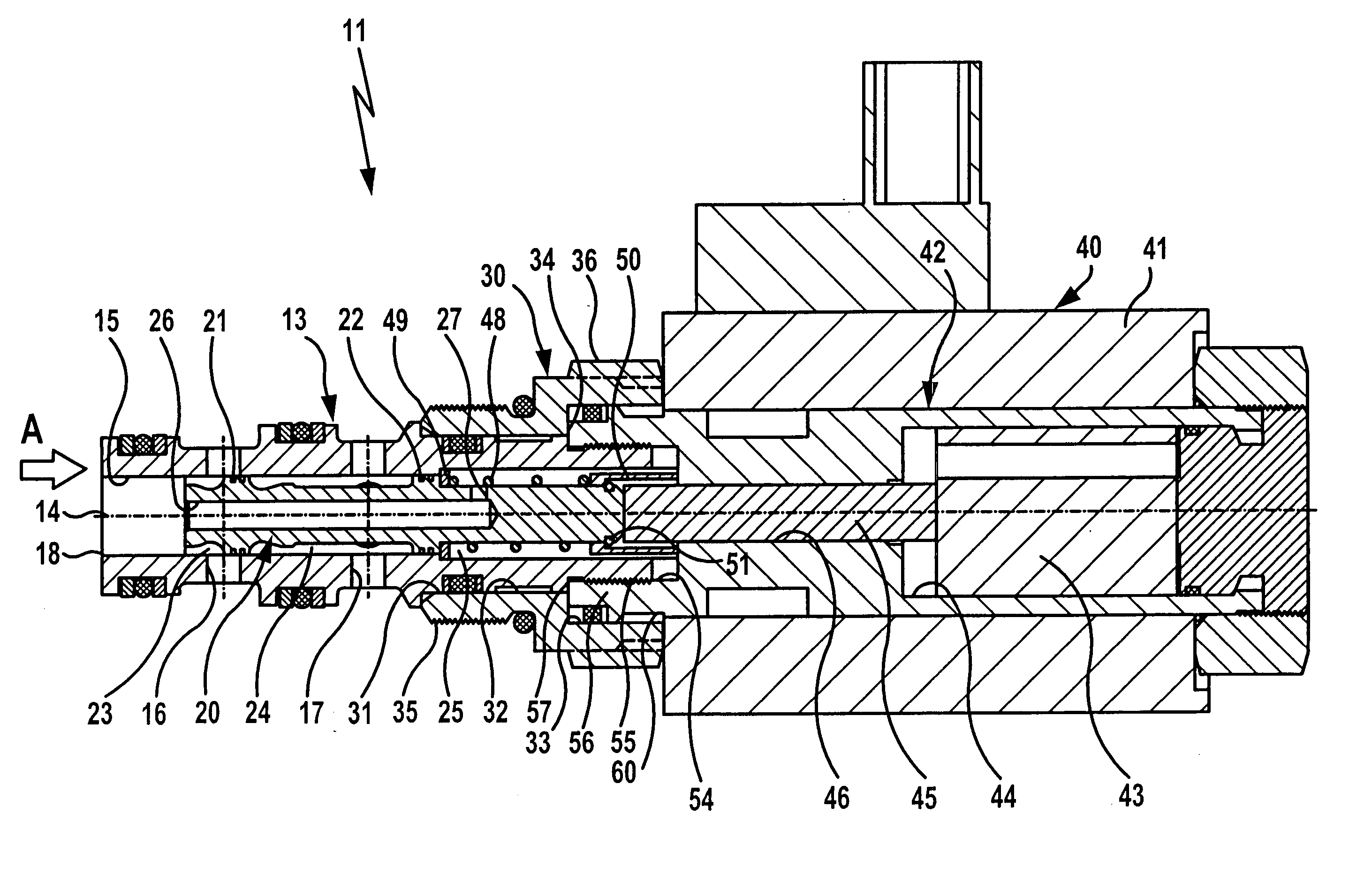
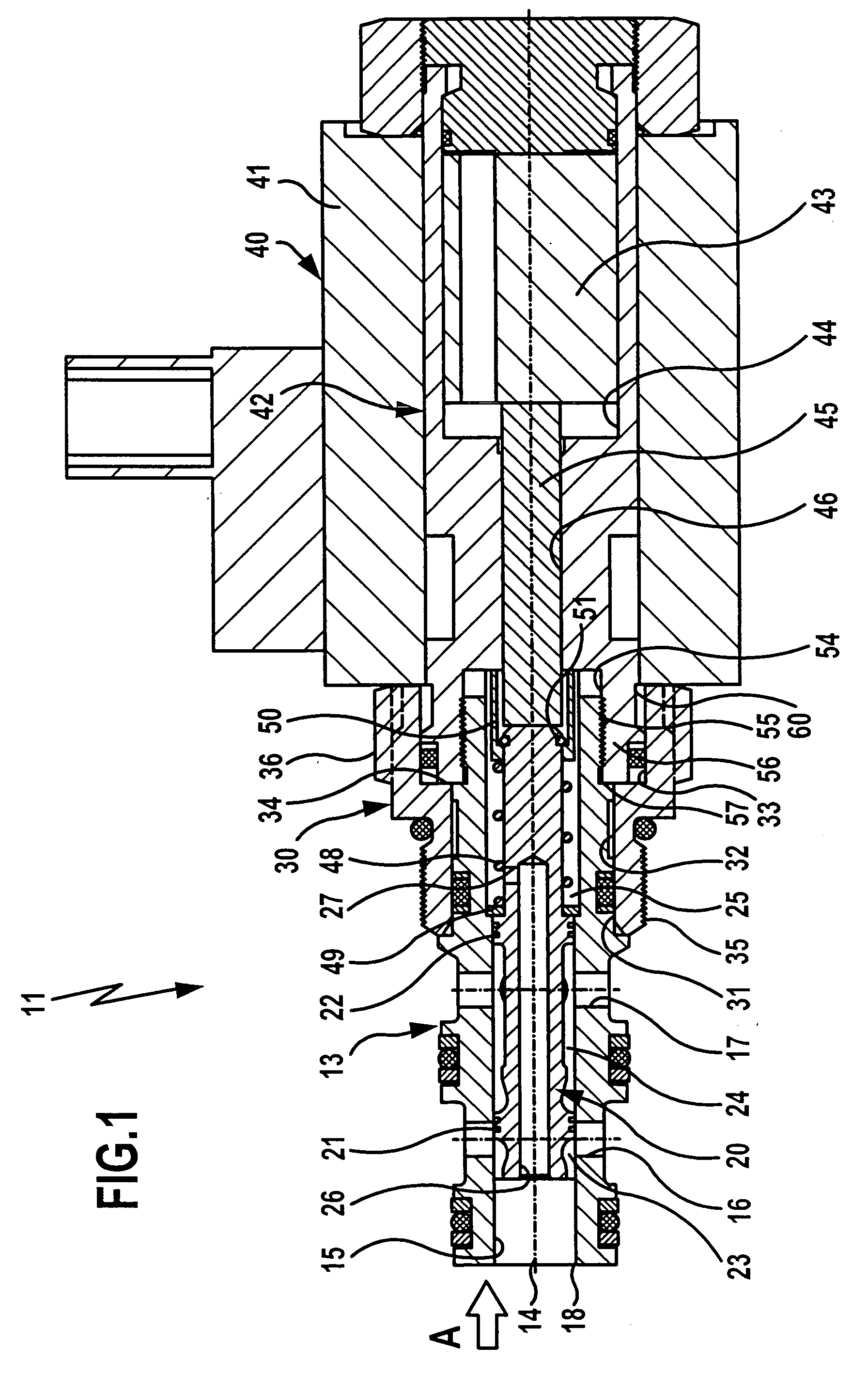
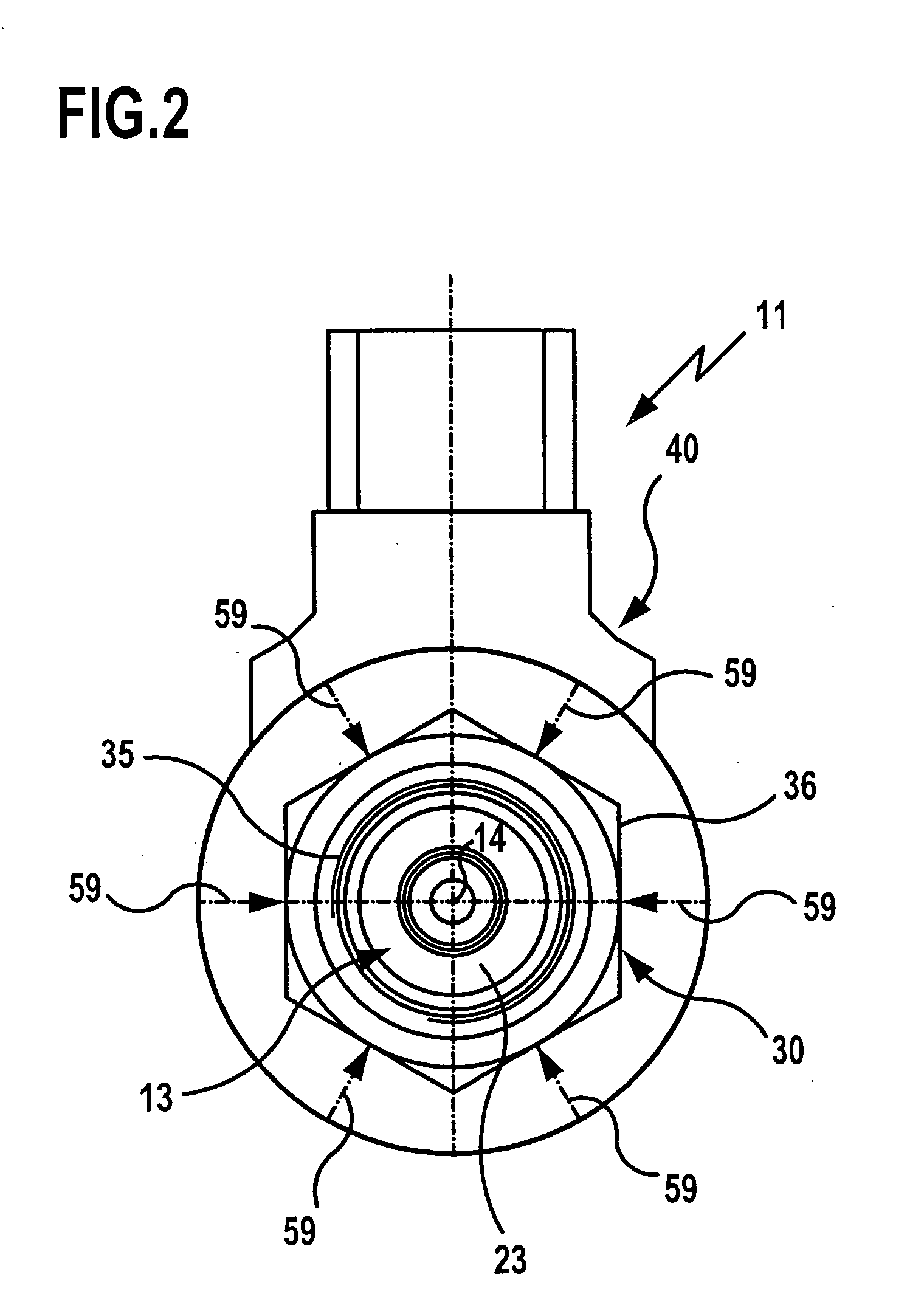
[0040]FIGS. 1 and 2 show in schematic representation an inventive screw-in valve which is generally designated by reference numeral 11. It is constructed as a 3 / 2-port directional control valve and comprises a sleeve 13 with a longitudinal bore 15 oriented coaxially with the longitudinal axis 14 of the sleeve 13 and with two parallel transverse bores 16 and 17 arranged in spaced relationship to each other with respect to the longitudinal axis 14. The longitudinal bore 15 defines at the end face a first connection opening 18 of the sleeve 13, and the transverse bores 16 and 17 define in the circumferential area of the sleeve 13 second and third connection openings.
[0041] A valve piston 20 is held for axial displacement, i.e., in the direction of the longitudinal axis 14, in the longitudinal bore 15 of the sleeve 13. The valve piston 20 is guided inside the longitudinal bore 15 by means of two guide seals 21 and 22 arranged in axially spaced relationship to each other, which are fitte...
second embodiment
[0052]FIG. 3 shows a screw-in valve in the form of a 3 / 2-port directional control valve, generally designated by reference numeral 70, which differs from the above-explained screw-in valve 11 in that the sleeve 13 is not screwed to the pole tube 42, but instead a snap ring connection is provided between the sleeve 13 and the pole tube sleeve 56. For this purpose, the sleeve 13 in the embodiment shown in FIG. 3 carries in its end area facing away from the first connection opening 18, with which it dips into the pole tube sleeve 56 of the pole tube 42, a snap ring 71, and the pole tube sleeve 56 has a corresponding ring groove 72 at the level of the snap ring 71. In the second embodiment shown in FIG. 3, the connection between the pole tube sleeve 56 and the screw-in component 30 is also made via a flange corresponding to the embodiment shown in FIGS. 1 and 2, so that a positive connection is also produced between screw-in component 30 and pole tube sleeve 56, with the connection enab...
fourth embodiment
[0055]FIG. 5 shows the inventive screw-in valve which is designated by reference numeral 90. This differs from the screw-in valve 80 shown in FIG. 4 in that the screw-in component 30 is integrally connected to the pole tube 42. This makes a particularly time-saving assembly of the screw-in valve possible.
PUM
 Abstract
Description
Claims
Application Information
 - R&D
- Intellectual Property
- Life Sciences
- Materials
- Tech Scout
- Unparalleled Data Quality
- Higher Quality Content
- 60% Fewer Hallucinations
Browse by: Latest US Patents, China's latest patents, Technical Efficacy Thesaurus, Application Domain, Technology Topic, Popular Technical Reports.
© 2025 PatSnap. All rights reserved.Legal|Privacy policy|Modern Slavery Act Transparency Statement|Sitemap|About US| Contact US: help@patsnap.com


