
Method for manufacturing ribbed archery bow limb portions and the ribbed archery bow limb portions produced thereby

a technology of ribbed archery and limbs, which is applied in the field of manufacturing the ribbed archery bow limbs produced thereby, can solve the problems of reducing the maximum limb operating stress level, reducing the fatigue life of the limb, and costly and time-consuming second-hand machining operations, etc., and achieves the effect of improving the limbs of the archery bow

Active Publication Date: 2005-06-30
BEAR ARCHERY
View PDF16 Cites 13 Cited by
  • Summary
  • Abstract
  • Description
  • Claims
  • Application Information

AI Technical Summary

Benefits of technology

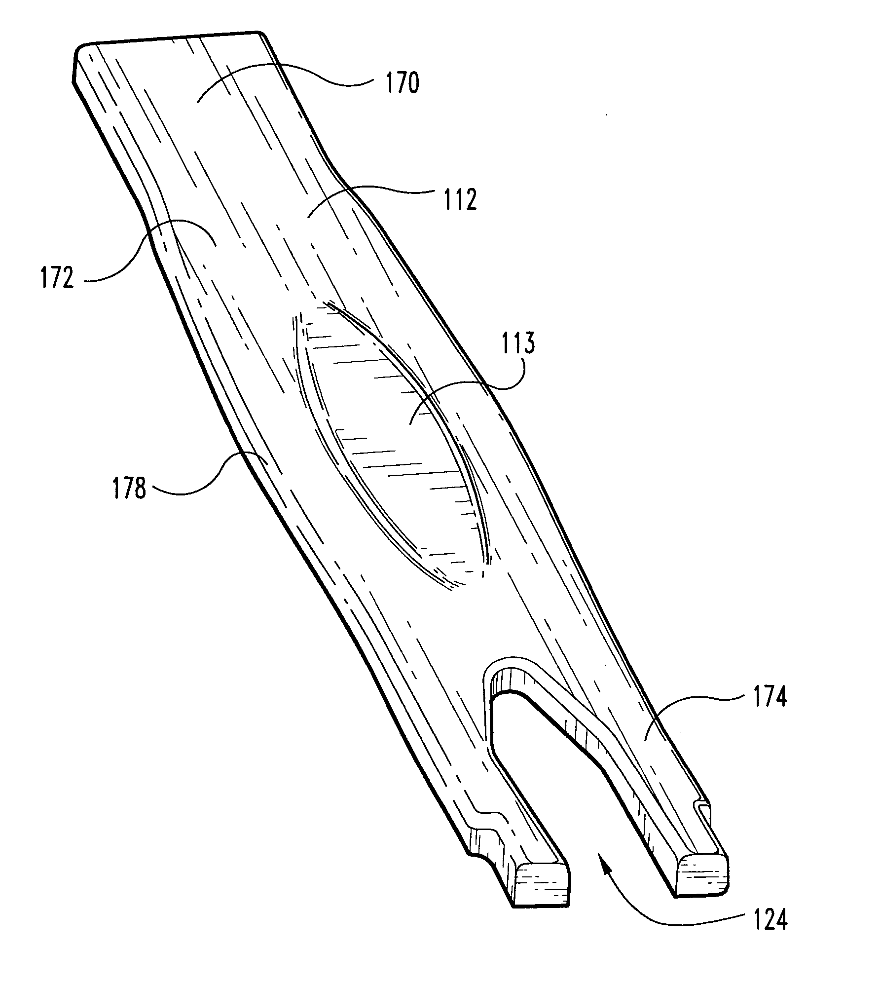
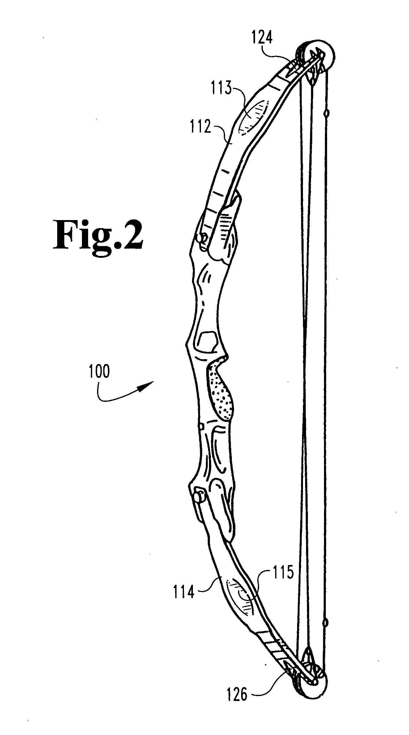
[0008] Typically a limb has a butt section or end attachable to a bow riser, a middle or hinge section and an opposing tip section or end. Preferably, the glass-to-resin ratio is substantially constant throughout the limb during forming. Typically this requires a substantially constant cross-sectional total area in the butt, hinge and tip sections. In a preferred embodiment, the present method and limb includes a longitudinal protruding rib section formed in the middle or hinge portion of the limb. This allows a narrowed front-profile to be presented in the hinge section, while maintaining the total cross-sectional area. In a further preferred embodiment, the limb, along with a longitudinal protruding rib section, is curved prior to assembly into an archery bow.
[0010] It is an object of this invention to provide an improved method of manufacturing compression molded archery bow limb portions, and to provide improved archery bow limb portions.

Problems solved by technology

In all such cases, the secondary machining operations are costly and time consuming.
Further, the machining operations result in the severing of load bearing fibers which reduces the maximum limb operating stress level and the fatigue life of the limbs.

Method used


Image

  • Method for manufacturing ribbed archery bow limb portions and the ribbed archery bow limb portions produced thereby
  • Method for manufacturing ribbed archery bow limb portions and the ribbed archery bow limb portions produced thereby
  • Method for manufacturing ribbed archery bow limb portions and the ribbed archery bow limb portions produced thereby

Examples


Embodiment Construction

[0027] For the purposes of promoting an understanding of the principles of the invention, reference will now be made to the embodiments illustrated and specific language will be used to describe the same. It will nevertheless be understood that no limitation of the scope of the invention is thereby intended, such alterations, modifications, and further applications of the principles of the invention being contemplated as would normally occur to one skilled in the art to which the invention relates.

[0028] A method according to the present invention forms a limb for use in an archery bow. A preferred method comprises inserting a moldable slug having a plurality of longitudinally oriented resin impregnated fiber filaments into a limb portion profiling mold. The mold consists of two halves, a first half containing one or more female cavities and a second half having one or more mating male sections. Preferably, the first half is profiled to provide the configuration of the front of the...


PUM


Abstract

Typically a limb for an archery bow has a butt section or end attachable to a bow riser, a middle or hinge section and an opposing tip section or end. In a preferred embodiment, the present method and limb includes a rib section formed in the middle or hinge portion of the limb. This allows a narrowed front-profile to be presented in the hinge section, while maintaining the total cross-sectional area. In one preferred method, at least one half of a mold is formed to define a rib section in the hinge section of the limb. Preferably the rib section runs longitudinally along the length of the hinge section, and may include a tapered profile along the edges and ends of the rib. In another preferred embodiment, the limb, including a rib section, is curved prior to assembly into an archery bow.

Description

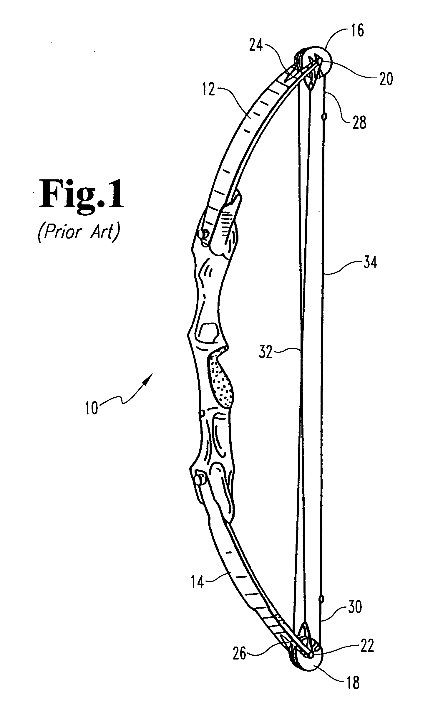
REFERENCE TO RELATED APPLICATIONS [0001] This application is a continuation-in-part of the prior-filed patent application Ser. No. 10 / 748,021 filed on Dec. 30, 2003.FIELD OF THE INVENTION [0002] The present invention relates generally to archery bows and more particularly pertains to an improved compression molded archery bow limb for use in bows and a method for manufacturing the same. BACKGROUND OF THE INVENTION [0003] Archery bow limbs perform the important function of storing energy when the archer draws the bowstring. When the bowstring is drawn, the pre-stressed bow limbs, which are typically made of resilient material, are further flexed to store additional energy. When the bowstring is released, the stored energy propels the arrow. In conventional compound bows, the limb is typically formed of a single element with a rectangular cross section, where one end is attached to the bow handle and the other end has a limb tip slot formed therein, in which a rotational member such a...

Claims


Application Information

Patent Timeline
IPC IPC(8): F41B5/10
CPCF41B5/10
Inventor GALLOPS, HENRY M. JR.
Owner BEAR ARCHERY
Learn More