
Brushless DC motor

a brushless dc motor and motor technology, applied in the direction of dynamo-electric machines, magnetic circuit rotating parts, magnetic circuit shapes/forms/construction, etc., can solve the problems of harmonic vibration or noise, poor energy efficiency, and deterioration of motor characteristics,

Inactive Publication Date: 2005-06-23
JTEKT CORP
View PDF12 Cites 23 Cited by
  • Summary
  • Abstract
  • Description
  • Claims
  • Application Information

AI Technical Summary

Benefits of technology

The design achieves improved energy efficiency, reduced vibration and noise, and easier motor design by separating magnetic paths, allowing for effective utilization of magnet torque and minimizing leakage flux, resulting in a more efficient and balanced torque output.

Problems solved by technology

However, according to the above-described conventional brushless DC motor utilizing the reluctance torque, there poses a problem explained below.
Therefore, the energy efficiency is poor.
Therefore, a characteristic of the motor is deteriorated and vibration or noise by harmonics are increased by that amount.
Therefore, design of the motor is very difficult.
Further, there also poses a problem that a magnetic flux density distribution becomes uniform at a gap between the rotor and the stator.
Further, according to the brushless DC motor of FIG. 47, a leakage magnetic flux flowing from one permanent magnet to a contiguous permanent magnet without interlinking with the stator coil, is so large that the leakage magnetic flux cannot be disregarded.
However, according to the above-described conventional technology, there poses the following problem.
The fact constitutes a factor of cost.
Further, when the motor is of a type in which a magnetic member of a rotor is present on an outer side of a magnet as shown by FIG. 50 for utilizing a reluctance torque, there also poses the following problem.
Therefore, the magnetic member at the commonly used portion is liable to fall to magnetic saturation.
Further, a magnetic flux distribution in an air gap between a rotor and a stator, becomes significantly nonuniform due to the magnetic flux related to the reluctance torque.
The fact deteriorates properties of the motor and causes vibration or noise by harmonics.

Method used


Image

  • Brushless DC motor
  • Brushless DC motor
  • Brushless DC motor

Examples


first embodiment

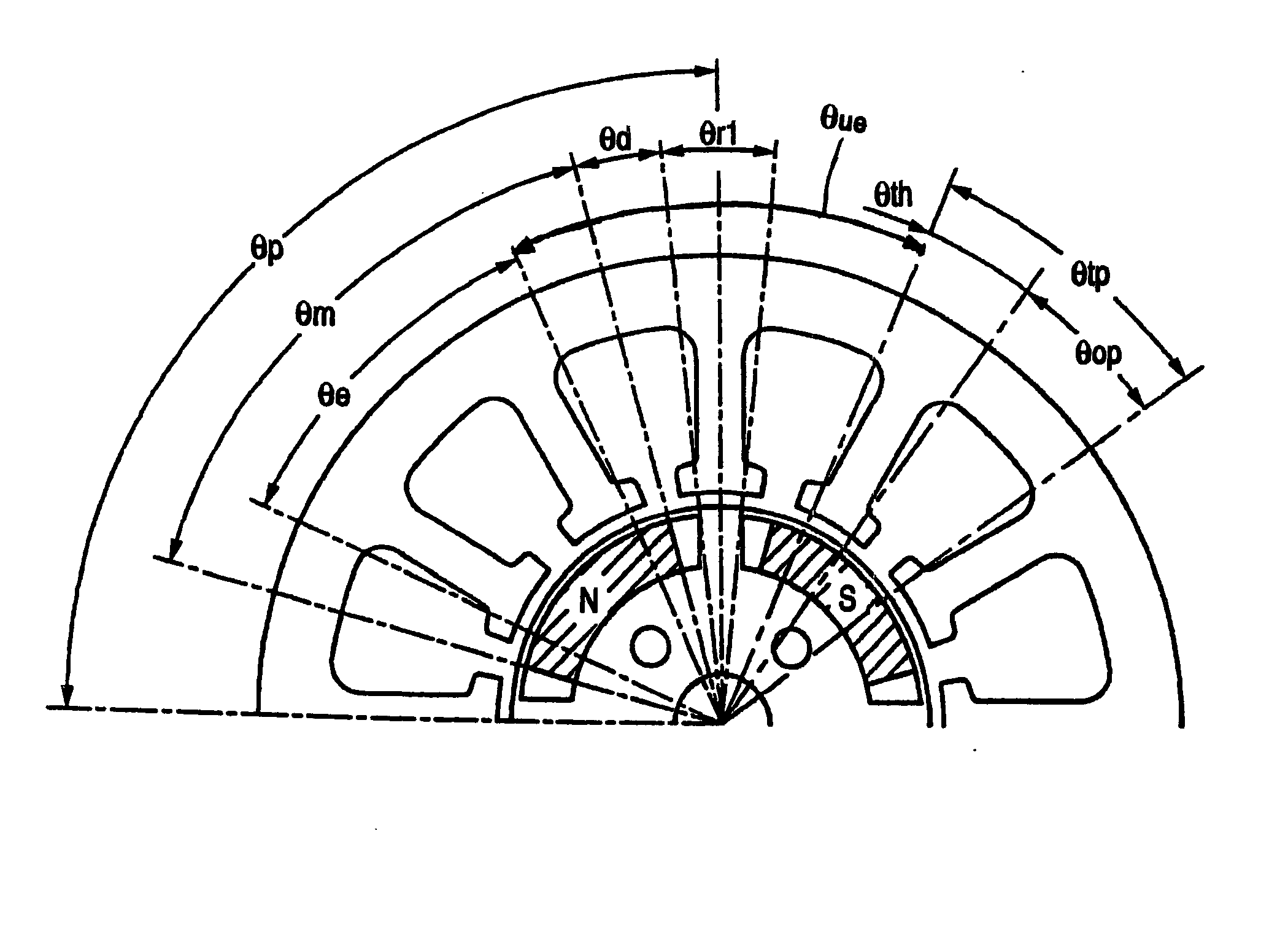
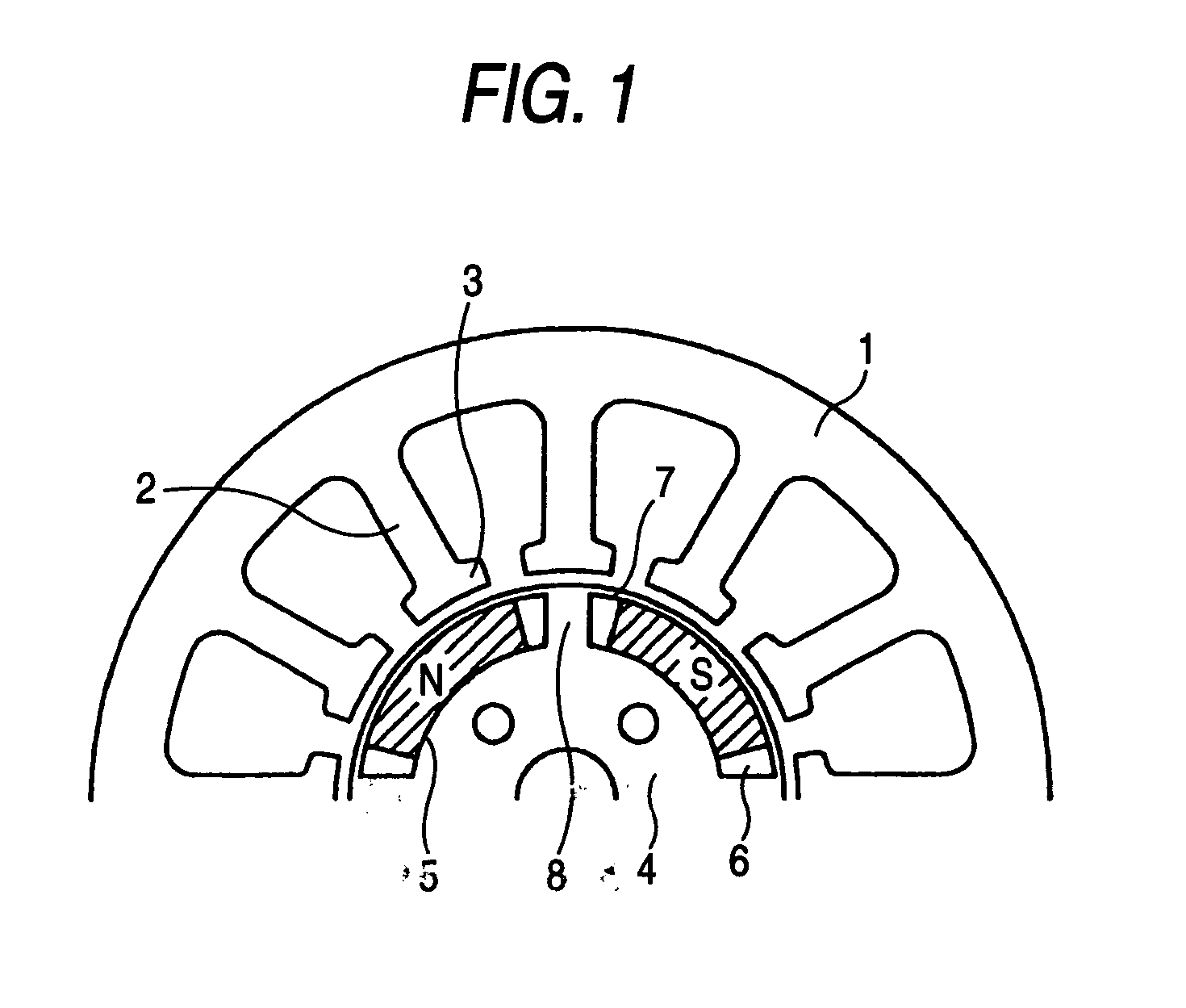
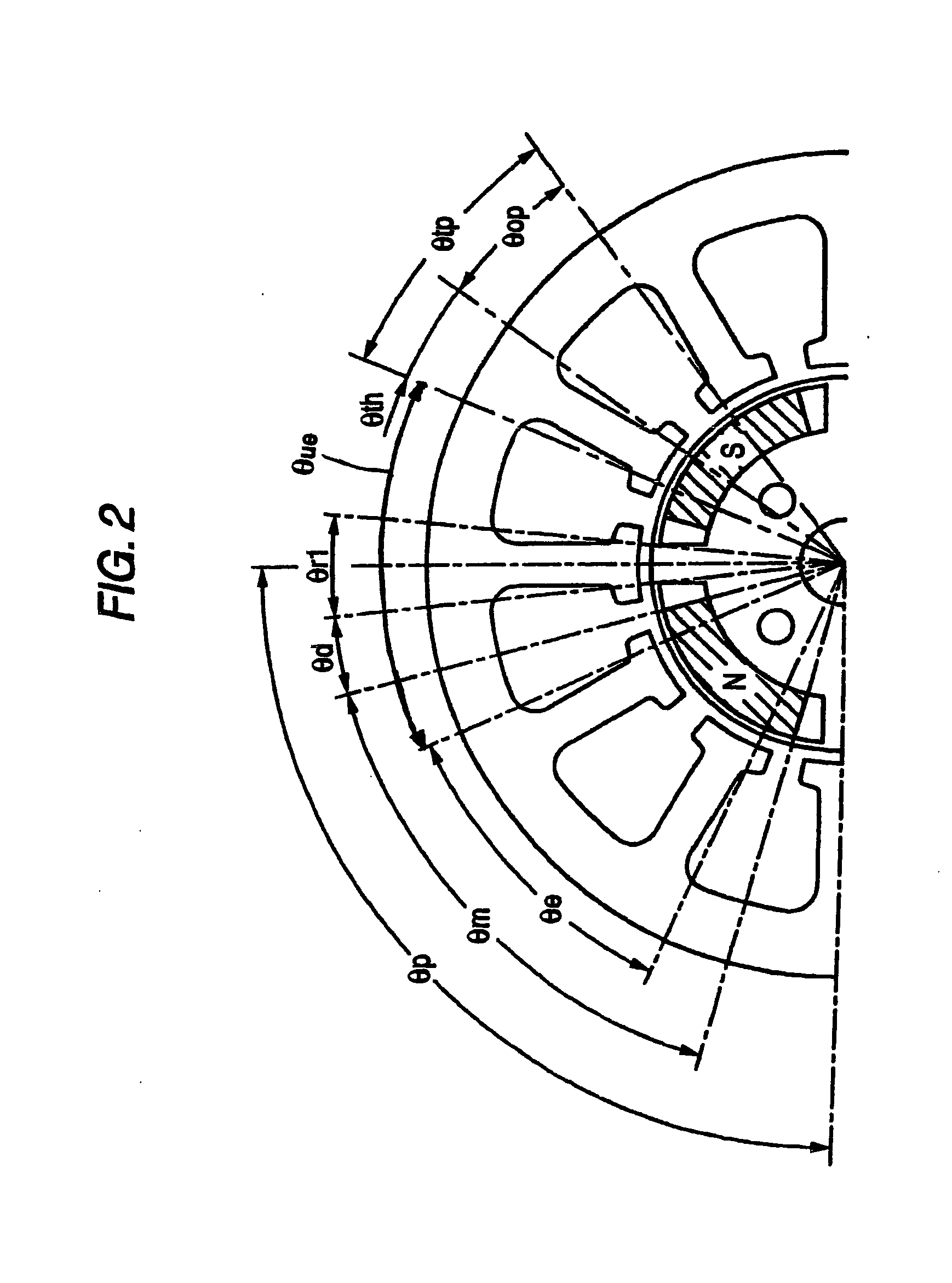
[0139] A detailed explanation will be given of embodiments embodying the invention in reference to the attached drawings as follows. The embodiment embodies the invention as a brushless DC motor constituted by a stator having 12 slots and a rotor having 4 poles. According to the embodiment, an angular range of an opening angle used in each of portions of the stator and the rotor, is defined by a portion facing an air gap (inner periphery in the stator, outer periphery in the rotor).

[0140] A brushless DC motor according to the embodiment is constituted by a structure as shown in FIG. 1. A stator 1 of the brushless DC motor is provided with 12 pieces of teeth 2. A front end of the respective tooth 2 is formed with a tip 3. Meanwhile, a rotor 4 is provided with 4 pieces of permanent magnets 5. The respective permanent magnet 5 is formed by a shape of a so-to-speak substantially circular arc along an outer periphery of the rotor 4. A respective magnet attaching hole 6 in the rotor 4 is...

second embodiment

[0176] A detailed explanation will be given of embodiments embodying a brushless DC motor according to the invention in reference to the attached drawings as follows. According to the embodiment, the invention is embodied as a brushless DC motor constituted by a stator of 12 slots and a rotor of 4 poles.

[0177] A brushless DC motor according to the embodiment is constituted by a structure as shown by FIG. 16. A stator 52 of the brushless DC motor includes 12 pieces of teeth 51 aligned at equal pitches in a circumferential direction. Meanwhile, a rotor 54 includes 4 pieces of magnets 53. The respective magnet 53 is formed by a shape of a so-to-speak substantially circular arc along an outer periphery of the rotor 54. A respective magnet attaching hole 55 at the rotor 54 is formed to be longer than the magnet 53 in the circumferential direction. The respective magnet 53 is attached to the center of the respective magnet attaching hole 55 in the circumferential direction. Therefore, th...

third embodiment

[0230] A detailed explanation will be given of embodiments embodying the invention in reference to the attached drawings as follows.

[0231] A brushless DC motor according to the embodiment is constituted as shown by FIG. 28. FIG. 28 is shown by omitting a lower half of the motor. A rotor 80 of FIG. 28 is provided with 4 pieces of magnets 81 and a pole pair number is 2. Therefore, an electric angle with regard to the rotor 80 is twice as much as a geometrical angle. The rotor 80 is formed with 4 of magnet attaching holes 82. The respective is attached with a single one of the magnet 81. There is present a magnetic member region 83 also on an outer side of the respective magnet 81 in the rotor 80. Further, there is present a bridge 84 connecting an outer side and an inner side of the magnet 81 by a magnetic member between the contiguous magnets 81. A stator 90 of FIG. 28 includes 12 pieces of teeth 91. Although windings are provided actually to the respective teeth 91, the windings ar...


PUM


Abstract

A bridge (8) in conformity with a tooth opening angle of the stator (1) is provided between a permanent magnet (5) and a permanent magnet (5) in a rotor (4), so that a magnetic flux for a reluctance torque is made to pass an inner side of the permanent magnet (5). An opening angle of each of ribs (7) on both sides of the permanent magnet (5) is set to be equal to or smaller than the teeth interval opening angle and equal to or larger than a half thereof. Thereby, reluctance of the rib (7) against a magnetic flux in a circumferential direction is increased and leakage of the magnetic flux of the permanent magnet (5) is prevented.

Description

BACKGROUND OF THE INVENTION [0001] The present invention relates to a brushless DC motor having a permanent magnet at a rotor thereof. Further in details, the invention relates to a brushless DC motor utilizing a reluctance torque for effectively utilizing the reluctance torque while preventing a cogging torque from increasing as less as possible. [0002] Conventionally, there is a brushless DC motor of this kind utilizing a reluctance torque having a constitution shown by, for example, FIG. 47. That is, according to a rotor 101 of a brushless DC motor of the drawing, a permanent magnet 102 is arranged on an inner side of an outer periphery to some degree. Therefore, a magnetic region 103 is present between the outer periphery of the rotor 101 and the permanent magnet 102. In driving the motor, as shown by an arrow mark of “q axis” in the drawing, a magnetic flux produced by a stator passes through the magnetic region 103 of the rotor 101. The magnetic flux generates a reluctance tor...

Claims


Application Information

Patent Timeline
Patent Type & Authority Applications(United States)
IPC IPC(8): H02K1/27H02K21/14
CPCH02K1/276H02K21/14H02K1/2766
Inventor MORI, SADAAKIINAYAMA, HIROHIDEISHIHARA, ATSUSHITAKAHASHI, TOMOFUMIKITABAYASHI, MINORUHORIE, TETSUO
Owner JTEKT CORP
Learn More