
Modular structure for energy absorption in head impacts on vehicle interiors

a module structure and vehicle interior technology, applied in the direction of vehicle safety arrangements, vibration dampers, pedestrian/occupant safety arrangements, etc., can solve the problems of limiting the geometry of the injection process used for manufacturing this type of plastic structures, limiting the possibility of shapes and designs, and increasing the cos

Inactive Publication Date: 2005-06-23
GRP ANTOLIN ING SA
View PDF11 Cites 34 Cited by
  • Summary
  • Abstract
  • Description
  • Claims
  • Application Information

AI Technical Summary

Benefits of technology

[0013] The object of the present invention is to eliminate the problems mentioned by means of a structure of the type described, constituted such that it allows a perfect adaptation to the surface to be protected, and additionally to introduce different shapes in a versatile manner.
[0014] The present invention develops a flexible and adaptable structure, formed by hollow bodies of different shapes and dimensions, joined together by flexible elements, without the need to use a uniform base plate. In addition to the high flexibility offered, this construction, allows the structure to be adaptable to the geometry of any support surface.
[0024] Easy adaptation of the solution to different shapes and / or different specifications, individually changing the number, the arrangement and the size of the deformable hollow bodies used in a simple manner, being able to optimise the structure for each vehicle, for each impact area and for each specific situation.
[0029] In short, the invention is basically focused on achieving a structure of deformable hollow bodies which have the capability to absorb energy when they collapse by being subjected to a determined force. In these structures, the hollow bodies forming them are joined together by means of flexible ribs allowing each deformable hollow body to behave independently of the rest of the structure. Furthermore, the structure is made up of clusters or modules which can be of equal or different dimensions, and which can also include hollow bodies of equal of different sizes, allowing very different shapes and structures to be obtained by simply changing the number and type of assembled elements.
[0030] Furthermore, said connection ribs between adjacent deformable hollow bodies are rigid enough to maintain the relative positions between them, but with enough flexibility to make the adaptation of the structure to surfaces with different shapes possible.

Problems solved by technology

All this is due to the fact that, on the one hand, a good placement of said plastic base on the support surface in the vehicle or in the component is required, and on the other hand, the injection process used for manufacturing this type of plastic structures conditions and limits its geometry.
They therefore present the same problem as ribbed structures, but as they have more complex geometries than the simple walls of a rib, the limitations in terms of possible shapes and designs are greater.
The main limitation is their cost, as well as the aforementioned limitations in the case of producing any of the types of the structures mentioned.
Furthermore, as has already been pointed out, the manufacturing process used for this type of structure conditions and limits its geometry.
Since the hollow bodies are connected by the base plate and by intermediate ribs and partitions, their capability of adaptation and of effectiveness are reduced.
This circumstance implies a problem when having to modify the initially defined structure according to the different requirements which need to be achieved for each specific situation and in the different application areas.
This problem is of special importance in the test and validation phases, in which each geometric modification to be validated implies expensive and relatively slow changes in design and in the manufacturing tools of the prototypes to be tested.
On the other hand, in all the analysed cases, since all the hollow bodies are fixed to the base plate and the latter has a predefined rigid shape, they are incapable of absorbing the geometric diffusions due to the usual tolerances in the working area, which prevents the structure from perfectly adapting itself to the zone to be protected, making the correct support thereof difficult and thus deducting efficacy from the system.

Method used


Image

  • Modular structure for energy absorption in head impacts on vehicle interiors
  • Modular structure for energy absorption in head impacts on vehicle interiors
  • Modular structure for energy absorption in head impacts on vehicle interiors

Examples


Embodiment Construction

[0036] The structure of the invention, as has been set forth, is comprised of a set of deformable hollow bodies with an open end section. These bodies are able to adopt a frusto-conical shape with an open lower base.

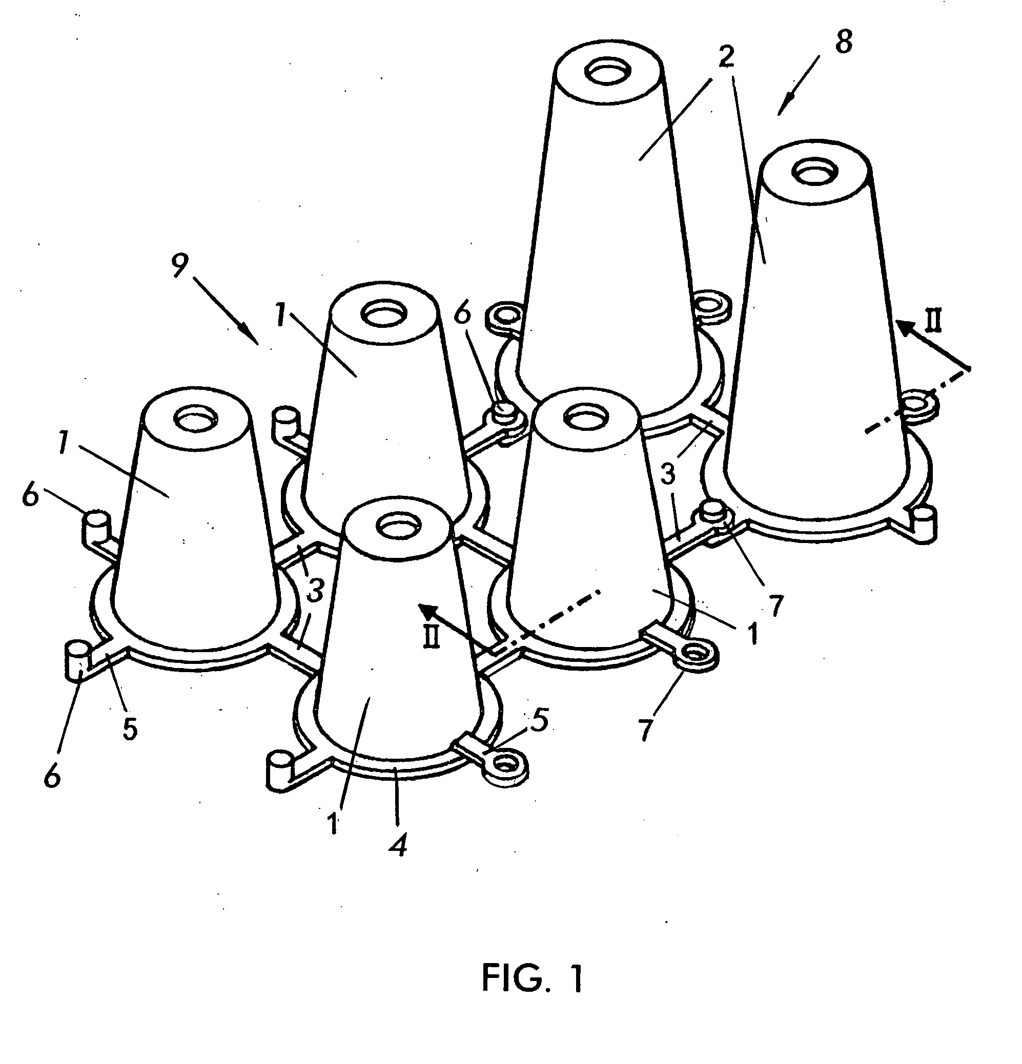
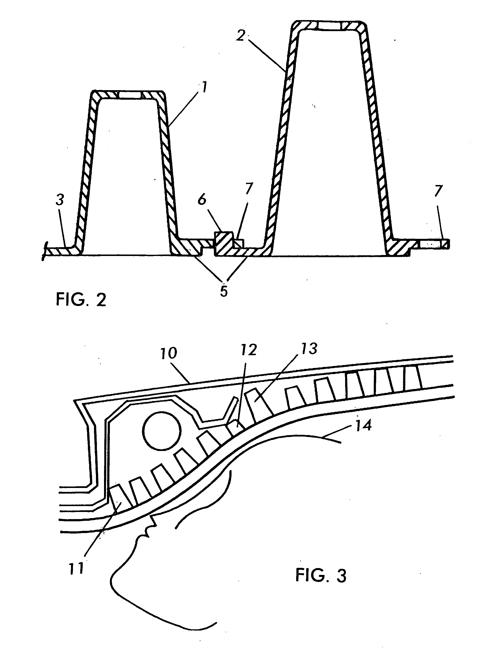
[0037]FIG. 1 shows a structure constructed according to the invention including two-dimensional frusto-conical shaped hollow bodies, minor ones referenced with number 1 and major ones referenced with number 2. The conical bodies 1 and 2 form two different clusters or modules. In each of one these clusters, the conical bodies, referenced with number 1 in one case and with number 2 in the other, are joined by intermediate flexible bridges generally referenced with number 3.

[0038] In the two clusters or modules, the frusto-conical bodies 2 are encircled from the open major base by an outlying rim 4 from which the flexible bridges 3 project.

[0039] Furthermore, according to another feature of the invention, flexible half bridges 5 finished off by mutual connection means, r...


PUM


Abstract

A modular structure for energy absorption useful in head impacts on vehicle interiors, comprising a set of deformable hollow bodies each having an open end section and the bodies are arranged in interconnected independent clusters. The hollow bodies in each cluster are joined by means of flexible bridges running between the open ends of adjacent bodies. The clusters are provided around their outline with flexible half bridges provided with mutual connection elements, a pin on one half bridge and a hole on the other half bridge.

Description

BACKGROUND OF THE INVENTION [0001] The present invention refers to a modular structure for energy absorption of impacts in vehicle interiors, intended to become part of the interior lining of the ceiling of a vehicle, for the purpose of reducing the risks of injury caused to an occupant or occupants of a vehicle upon impact against the internal surface of the ceiling thereof. [0002] The structure of the invention is applicable to all those parts of a vehicle interior susceptible to undergoing head impact of the occupants of said vehicle, especially in the case of accidents. [0003] Until today, different types of solutions for protecting the body of the occupants in case of accident have been used, reducing the injuries caused by impact against them in any part of the vehicle. [0004] All these solutions achieve their objective by means of the management of the kinetic energy generated and transmitted to the occupants during an impact, either by absorption of part of that energy or by...

Claims


Application Information

Patent Timeline
Patent Type & Authority Applications(United States)
IPC IPC(8): B60R21/04F16F7/12
CPCB60R21/04F16F7/12B60R2021/0442B60R2021/0414
Inventor SOTO BAILON, ARTUROABAJO ALONSO, JULIO CESAR
Owner GRP ANTOLIN ING SA
Learn More