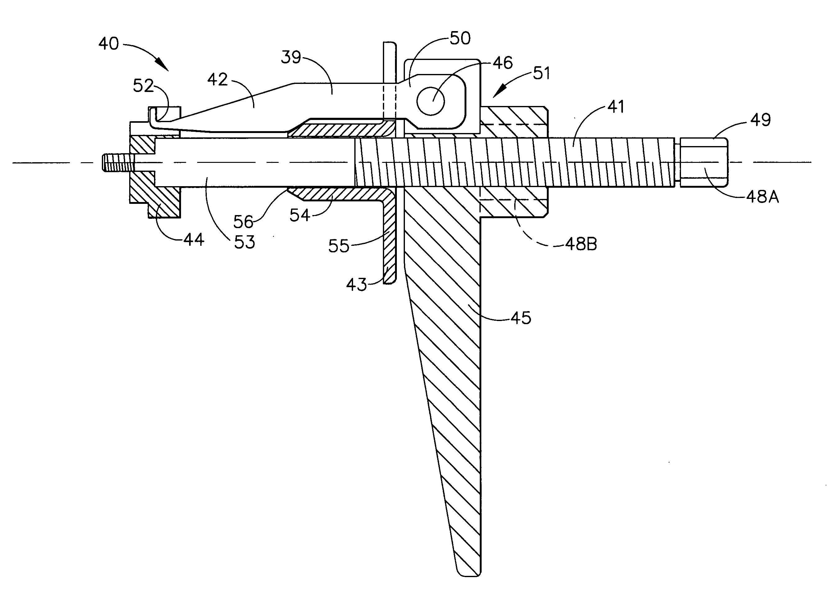
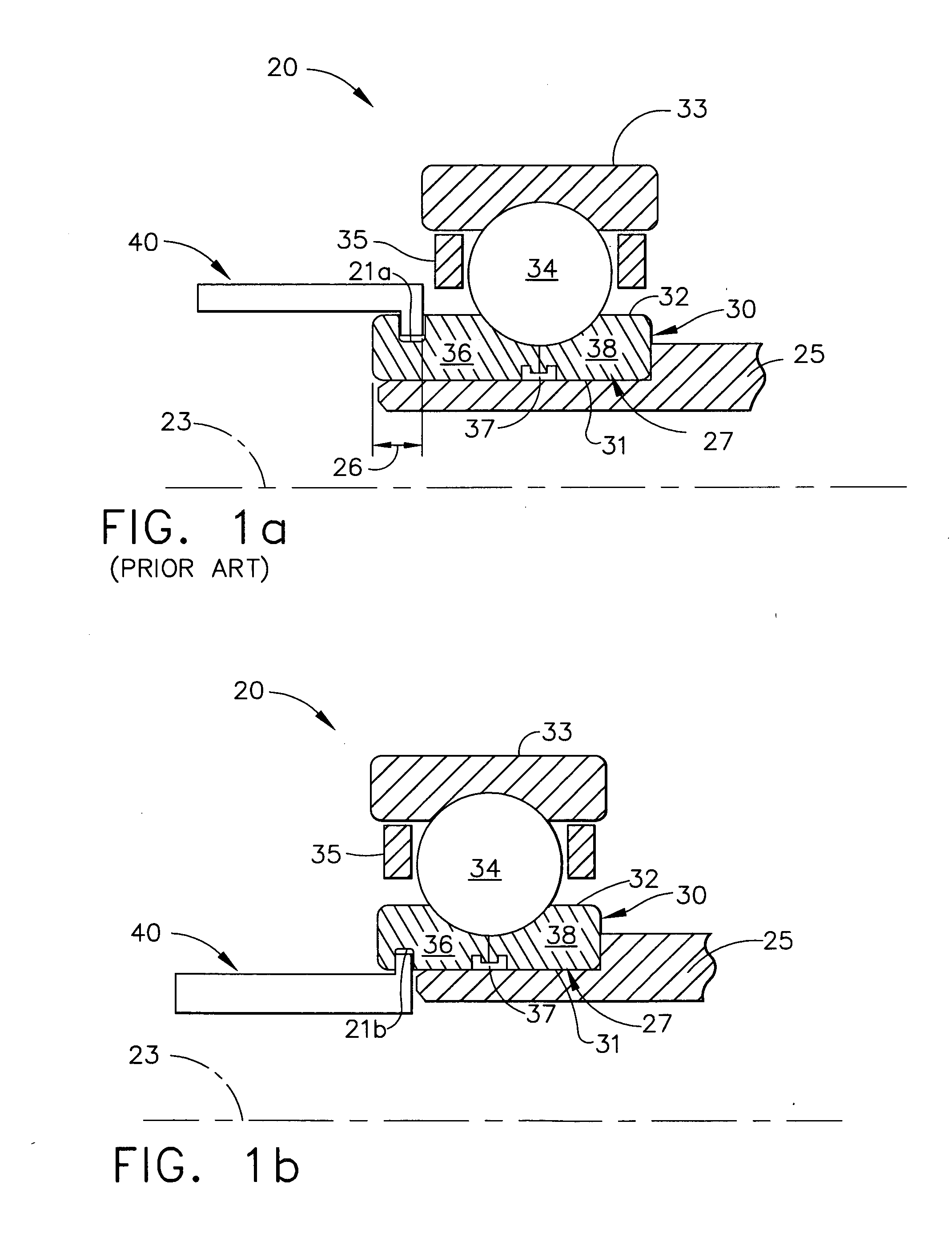
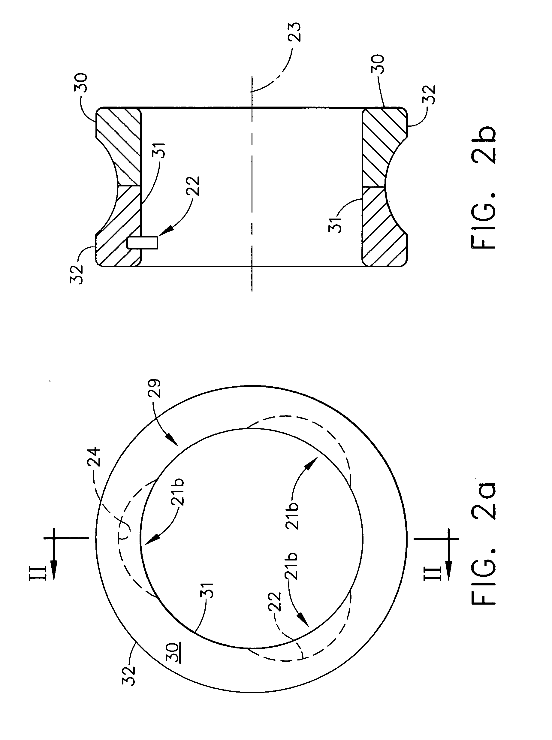
Compact removal feature and removal tool for rolling element bearings

a technology of rolling element bearings and features, which is applied in the direction of bearing repair/replacement, manufacturing tools, bearing rigid support, etc., can solve the problems of bearing not being reusable, destructive methods may not be desirable, and overload of thrust damage to the bearing

Inactive Publication Date: 2005-06-23
HONEYWELL INT INC
View PDF22 Cites 19 Cited by
  • Summary
  • Abstract
  • Description
  • Claims
  • Application Information

AI Technical Summary

Problems solved by technology

For some applications, these destructive methods may not be desirable and other methods have been disclosed.
For bearings that are interference (press) fitted onto a shaft, thrust overload may damage the bearing.
Additionally, the gripping links will damage the bearing raceway rendering the bearing not reusable.
Further, the described tool is not useful for bearings having ball separators because the links must fit between the balls to engage the outer race.
Damage to parts may occur due to the high radial forces needed to drive the wedges behind the bearing race/sleeve.
Although, the described tool may be used to remove some bearing outer races, it is not useful for bearing assemblies having the inner ring press-fitted onto a shaft.
Further, the use of a slide hammer to exert axial force may result in part damage for

Method used


Image

  • Compact removal feature and removal tool for rolling element bearings
  • Compact removal feature and removal tool for rolling element bearings
  • Compact removal feature and removal tool for rolling element bearings

Examples


Embodiment Construction

[0024] The following detailed description is of the best currently contemplated modes of carrying out the invention. The description is not to be taken in a limiting sense, but is made merely for the purpose of illustrating the general principles of the invention, since the scope of the invention is best defined by the appended claims.

[0025] The present invention generally provides removal features and removal tools for rolling element bearings and methods for producing the same. The removal features and removal tools produced according to the present invention may find beneficial use in many industries including aerospace, automotive, and machine tools. The removal features and removal tools of the present invention may be beneficial in applications including manufacturing and repair of automotive and aerospace components, such as engines, drivetrains, transmissions, and gearboxes. The present invention may be beneficial in machine tool applications. This invention may be useful i...


PUM

PropertyMeasurementUnit
Lengthaaaaaaaaaa
Lengthaaaaaaaaaa
Widthaaaaaaaaaa

Abstract

A compact removal feature comprises a plurality of recesses, such as radius slots, on an inner diameter (ID) of a bearing inner ring. The removal tool can engage the removal feature and remove the entire bearing assembly without damage to the parts. The placement of the removal feature on the bearing inner ring ID allows for a reduction in inner ring length (and weight) while maintaining bearing assembly integrity.

Description

GOVERNMENT INTERESTS [0001] The invention was made with Government support under contract number N00019-01-C-3002 under the Joint Strike Fighter (JSF) program. The Government has certain rights in this invention.BACKGROUND OF THE INVENTION [0002] The present invention generally relates to rolling element bearings and, more particularly, to removal features and removal tools for rolling element bearings. [0003] Rolling element bearings have been used extensively in many products such as engines, transmissions, drivetrains, gearboxes, and machine tools. Rolling element bearings may comprise inner and outer bearing rings and bearing balls or rollers there between. The rolling element bearing may be positioned within the product such that the inner diameter of the rolling element bearing is in contact with a bearing shaft. The rolling element bearing may be removed for product disassembly or bearing replacement. Removal methods and removal tools have been described. [0004] Ball bearing ...

Claims


Application Information

Patent Timeline
IPC IPC(8): B25B27/06
CPCB25B27/062Y10T29/49696F16C19/06F16C33/586F16C33/60Y10T29/5387Y10T29/49822Y10T29/53848Y10T29/49815Y10T29/49698Y10T29/53865Y10T29/53861Y10T29/53857Y10T29/53874F16C35/062F16C2237/00F16C2300/02
Inventor BRIDGES, ERIC B.FROST, CRISTOPHER
Owner HONEYWELL INT INC
Why Eureka
Try Eureka