
Method of manufacturing a substrate for an electronic device by using etchant and electronic device having the substrate

a technology of electronic devices and substrates, applied in the field of etchant, can solve the problems and achieve the effects of poor yield, increased cost, and long manufacturing process

Inactive Publication Date: 2005-06-16
LG DISPLAY CO LTD
View PDF28 Cites 10 Cited by
  • Summary
  • Abstract
  • Description
  • Claims
  • Application Information

AI Technical Summary

Benefits of technology

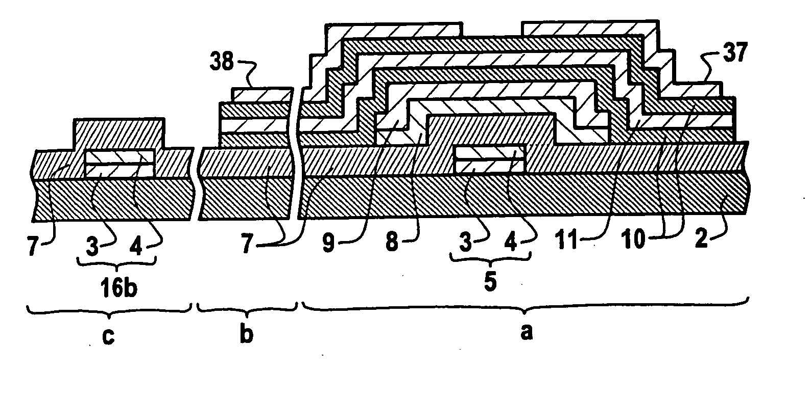
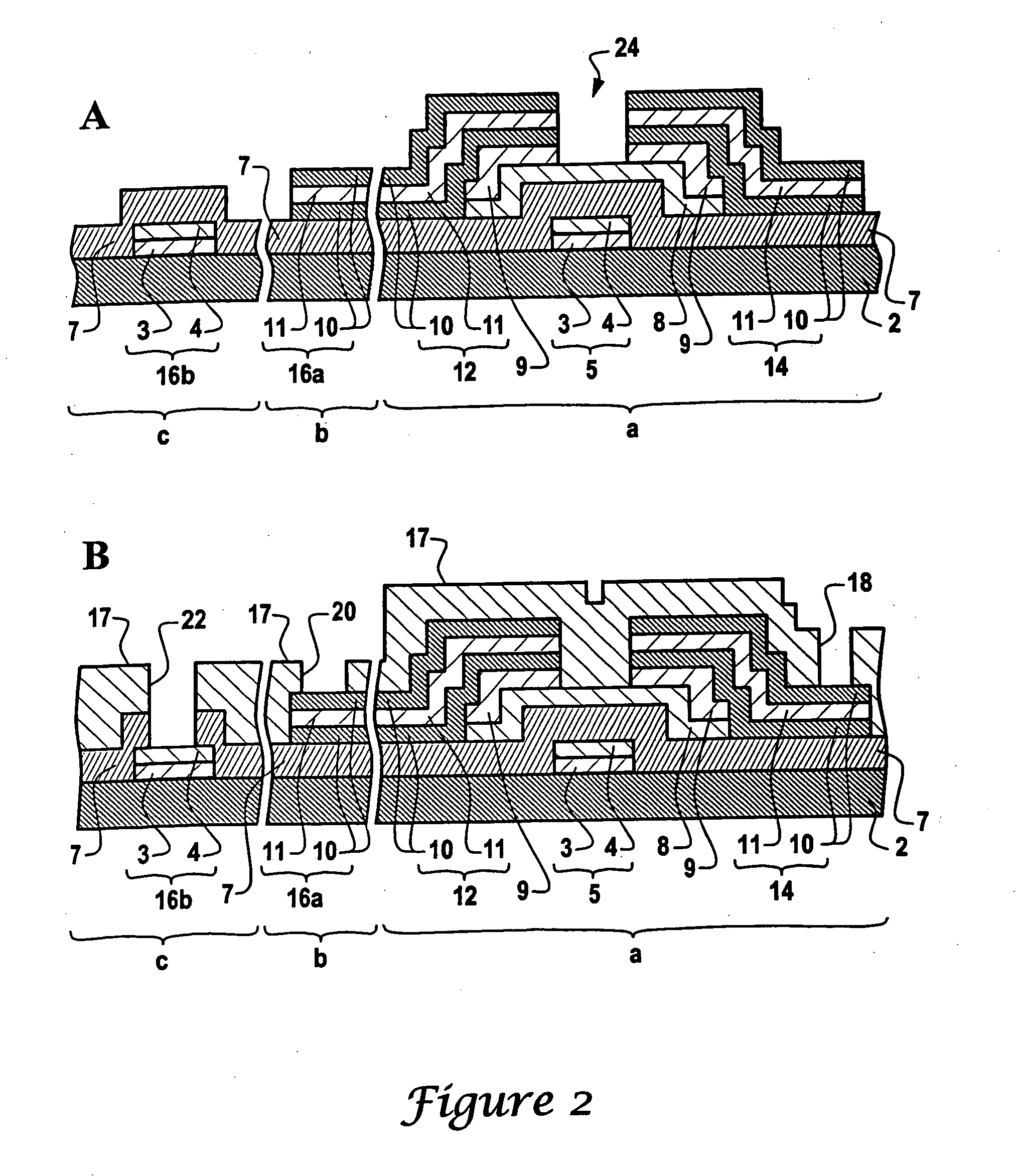
[0012] By the way, in the conventional method of manufacturing a substrate for an electronic device which is provided with the different metal stacked layer, the yield will be bad, the manufacturing process will be lengthened, and the cost will rise because at least two etching processes are needed. Further if adding etching were executed as mentioned above, the Mo layer in the upper layer should be a little more quickly etched than the Al layer in the lower layer, and as a result, as shown in FIG. 14C, the Al layer in the lower layer would be projected, and it is difficult to control a line width of wiring in the upper and lower layers.
[0013] Also, another method of forming a gate electrode in the different metal stacked layer, as shown in FIG. 15A, comprises the steps of: providing an Al layer 84a on the substrate 83; coating photoresist 97 on the surface of Al layer 84a; executing photolithography; and etching, as shown in FIG. 15B, so that an Al layer 84a of a desired line width is obtained. Subsequently the method comprises the steps of: covering the Al layer 84a by a Mo layer 84b, as shown in FIG. 15C; forming b

Problems solved by technology

By the way, in the conventional method of manufacturing a substrate for an electronic device which is provided with the different metal stacked layer, the yield will be bad, the manufacturing process will be lengthened, and the cost will rise because at least two etching processes are needed.
Further if adding etching were executed as mentioned above, the Mo layer in the upper layer should be a little more quickly etched than the Al layer in the lower layer, and as a result, as shown in FIG. 14C, the Al layer in the lower layer would be projected, and it is difficult to control a line width of wiring in the upper and lower layers.
By the way, at least a double etching process is needed like the conventional method, so that a problem is generated in this method, also.
As a result it is difficult to control the line width of wiring in the upper layer and lower layer.

Method used


Image

  • Method of manufacturing a substrate for an electronic device by using etchant and electronic device having the substrate
  • Method of manufacturing a substrate for an electronic device by using etchant and electronic device having the substrate
  • Method of manufacturing a substrate for an electronic device by using etchant and electronic device having the substrate

Examples


embodiment 1

[0087] The relation between the HIO4content of an etchant, and the potential difference between the Al electrode and the Ti electrode is investigated by using the electrode-electric potential measuring instrument as follows.

[0088] Etchant is filled in a container, an Al electrode and a Ti electrode are immersed in the etchant as both electrodes, a voltage is applied by a source, and then the potential difference between both electrodes is measured. HF of 0.3wt %, H2SO4 of 0.1 mol / l (0.54 wt %) is used as the etchant, and HIO4 has range of 0.05 wt %-2.0 wt %. The result is shown in FIG. 8.

[0089] In the result shown in FIG. 8, in the case that the HF content of the etchant is 0.3 wt % and the H2SO4 content is 0.1 mol / l, if the HIO4 content is 0.6 wt % or less, the potential difference between the Al electrode and the Ti electrode (ΔE) should be 0.4V or less. In the case of having the potential difference (ΔE) of 0.4V, the weight ratio of HIO4 to HF is 2 or less so that the weight ra...

embodiment 2

[0090] The relationship between the HF content of the etchant and the potential difference between the Al electrode and the Ti electrode, and side etching amount (ΔL) when a stacked layer of the Al layer and Ti layer is etched by using the etchant, is investigated as follows.

[0091] In the HF content of the etchant and the potential difference between the Al electrode and the Ti electrode, embodiment 2 is same as embodiment 1 except that the HIO4 content of the etchant is 1.5 wt %, H2SO4 is 1 mol / l (5.4 wt %) and HF is 0.1 wt %-0.8 wt %. The result is shown in FIG. 9.

[0092] And, the side etching amount is measured when a stacked layer formed from an Al layer having a thickness of 1300 Å and a Ti layer having a thickness of 500 Å is uniformly etched by using the etchant.

[0093] The result is shown in FIG. 10.

[0094] In the results shown in FIG. 9 and FIG. 10, in the case that the HIO4 content of the etchant is 1.5 wt %, and H2SO4 is 1 mol / l, if the HF content is 0.65wt % or more, th...

embodiment 3

[0095] Embodiment 3 is same as embodiment 1 except that the HIO4 content of the etchant is 0.05 wt %, HF is 0.03 wt % and H2SO4 is 0 wt %-0.54 wt %, as the H2SO4 content of etchant and the difference in potential between Al electrode and Ti electrode.

[0096] The result is shown in FIG. 11.

[0097] In the result shown in FIG. 11, in the case that the HF content of the etchant is 0.03 wt % and the HIO4 content is 0.05 wt %, if H2SO4 were 0.05wt % or less, the potential difference between the Al electrode and the Ti electrode (ΔE) becomes 0.4V or less. Therefore the lower limit of the weight ratio of H2SO4 is 0.05 wt %.

[0098] As mentioned hereto, an etchant according to the present invention has the advantage that each metal layer composing a stacked layer of a Ti layer or Ti alloy layer as another metal layer accumulated on an Al layer or Al alloy layer having low resistance can be etched to a substantially equal etching rate by only etching the structure one time.

[0099] Also, accord...


PUM

PropertyMeasurementUnit
Electric potential / voltageaaaaaaaaaa
Weight ratioaaaaaaaaaa
Electrical resistanceaaaaaaaaaa

Abstract

In the case that a stacked layer, in which another metal layer is stacked on an Al layer or Al alloy layer having a low resistance, is used as a wiring material, an etchant is provided which can etch to a substantially equal etching rate by executing only one etching on the each metal layer composing the stacked layer. A method of manufacturing a substrate for an electronic device uses the etchant, producing an electronic device having the substrate. In order to achieve the object, the etchant has fluoric acid, periodic acid and sulfuric acid wherein the total weight ratio of the fluoric acid and periodic acid is 0.05˜30 wt %, the weight ratio of the sulfuric acid is 0.05˜20 wt %, the weight ratio of periodic acid to fluoric acid is 0.01˜2 wt %. Also each layer of wiring(5,12,14) formed by stacking Al layer or Al alloy layer and Ti layer or Ti alloy layer can be uniformly etched to substantially equal etching rate by the etchant.

Description

[0001] This application claims the benefit of Japanese Patent Application No. 1998-303057, filed on Oct. 23, 1998, which is hereby incorporated by reference for all purposes as if fully set forth herein. BACKGROUND OF THE INVENTION [0002] The present invention relates to an etchant, a method of manufacturing a substrate for electronic device by using an etchant, and an electronic device having the substrate, and especially an etchant in which each layer of wiring formed by stacking an Al layer, or Al alloy layer, and a Ti layer, or Ti alloy layer, can be uniformly etched to a substantially equal etching rate by the etchant. [0003] Al as a wiring material has an advantage of having low resistance, and it is frequently used as the wiring material of an electrode etc. on a substrate of an electronic device. [0004] As an example of the electronic device, FIG. 12 is a plan view showing a thin film transistor in a conventional thin film transistor LCD. [0005] The thin film transistor 82 c...

Claims


Application Information

Patent Timeline
IPC IPC(8): C23F1/02H01L21/306C23F1/20G02F1/136H01L21/308H01L21/3213H01L21/336
CPCC23F1/02H01L29/66765H01L21/32134C23F1/20G02F1/136
Inventor JO, GYOO CHUL
Owner LG DISPLAY CO LTD
Learn More