Rotatable cutting tool

a cutting tool and rotatable technology, applied in the field of rotatable cutting tools, can solve the problems of excessive wear of knives, fracturing of wood, rough or uneven work surfaces,

Inactive Publication Date: 2005-06-16
MOLDER SERVICES
View PDF33 Cites 7 Cited by
  • Summary
  • Abstract
  • Description
  • Claims
  • Application Information

AI Technical Summary

Benefits of technology

[0015] According to another embodiment of the present invention, the rotating cutting tool includes first and second cavities that define different shear angles so that a knife can be selectively supported in the cavities at the different shear angles. For example, each cavity can have a shear angle that is between about 0 and 10 degrees relative to the longitudinal axis of the body. In particular, the first cavity can have a shear angle of about 5 degrees and a hook angle between about 10 and 12 degrees, and the second cavity can have shear angle that is about 10 degrees and a hook angle that is about 20 degrees. The body can define additional cavities that correspond to the first and second cavities so that multiple knives can be supported in each configuration.

Problems solved by technology

An improper hook or shear angle can result in fracturing of the wood, rough or uneven work surfaces, excessive wear of the knives, and other poor cutting characteristics.
Because the hook and shear angle of the knives is typically determined by the configuration of the cavities of the cutterhead, adjusting the hook or shear angle can require changing the knives and / or cutterhead, which can be time consuming, thereby reducing machine efficiency.
Additionally, keeping multiple cutterheads with different hook and shear angles on hand for different processes requires a disadvantageous additional expense.
However, the provision of additional cavities that are not occupied by knives can change the rotational and balance characteristics of the cutterhead and the tool can be damaged if used without securing appropriate fillers in the cavities that are not being used to secure knives.
If fillers are positioned in the unused cavities, there is a risk that improperly sized or weighted fillers will be used, thereby increasing the risk of tool failure and damage to nearby equipment.
Additionally, the milled pockets provided for the bolts can also adversely affect the strength of the tool as well as the rotational and weight characteristics of the tool.
Further, if the bolts are not properly tightened, the knives and / or fillers may become loose during operation and be projected from the tool.

Method used


Image

  • Rotatable cutting tool
  • Rotatable cutting tool
  • Rotatable cutting tool

Examples


Embodiment Construction

[0030] The present inventions now will be described more fully hereinafter with reference to the accompanying drawings, in which some, but not all embodiments of the inventions are shown. Indeed, these inventions may be embodied in many different forms and should not be construed as limited to the embodiments set forth herein; rather, these embodiments are provided so that this disclosure will satisfy applicable legal requirements. Like numbers refer to like elements throughout.

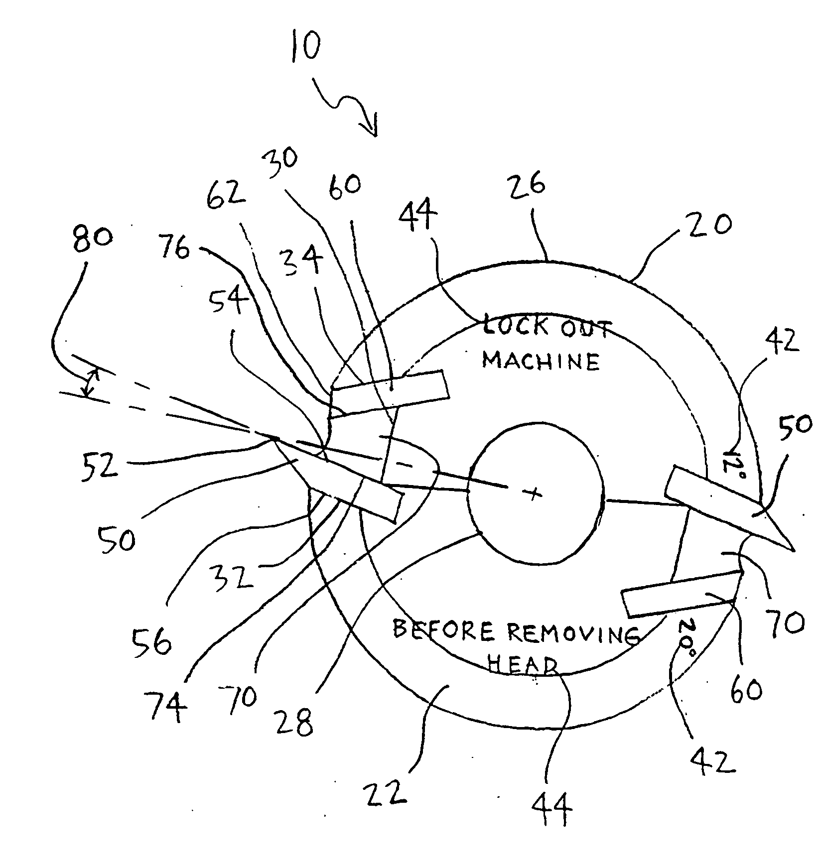
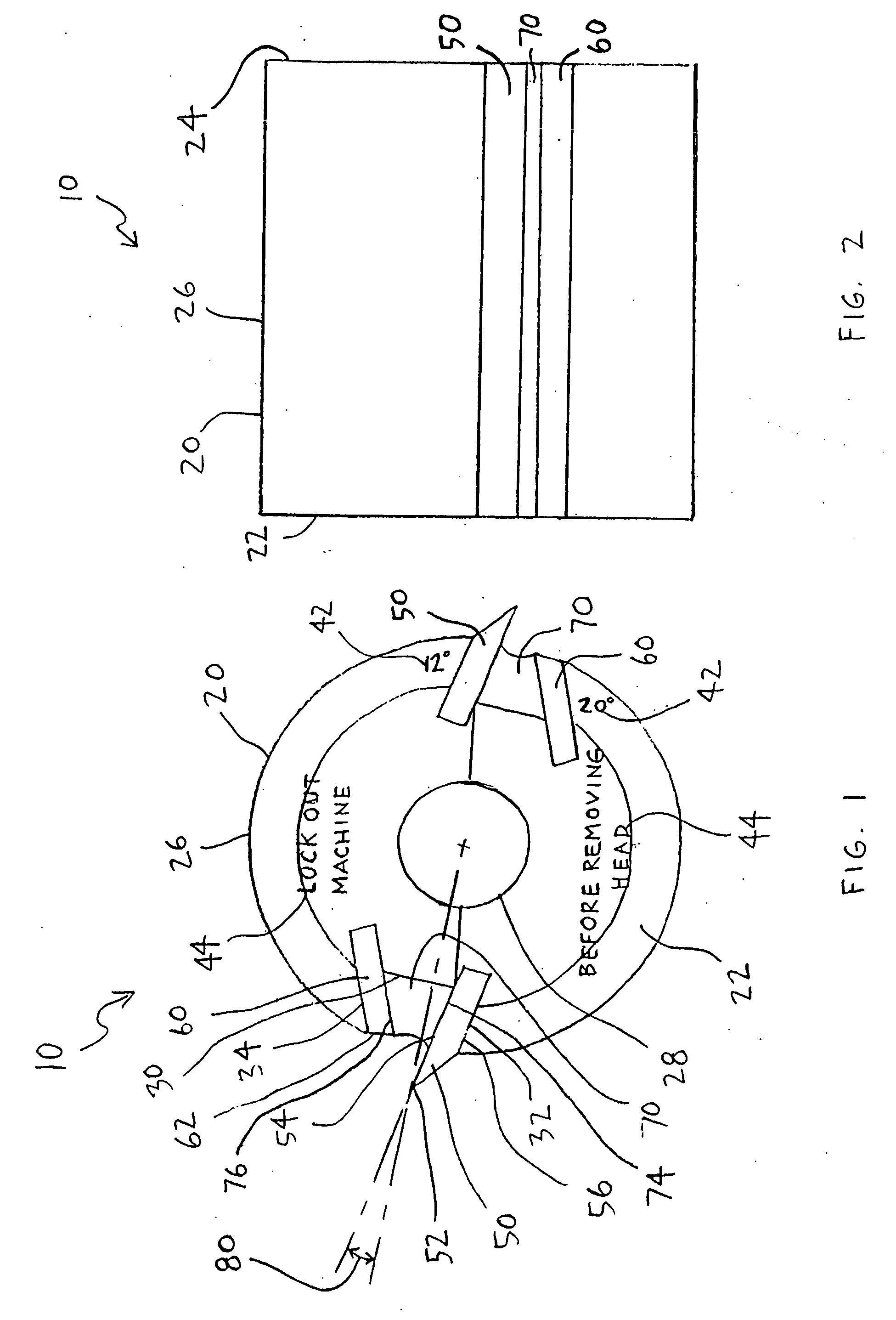
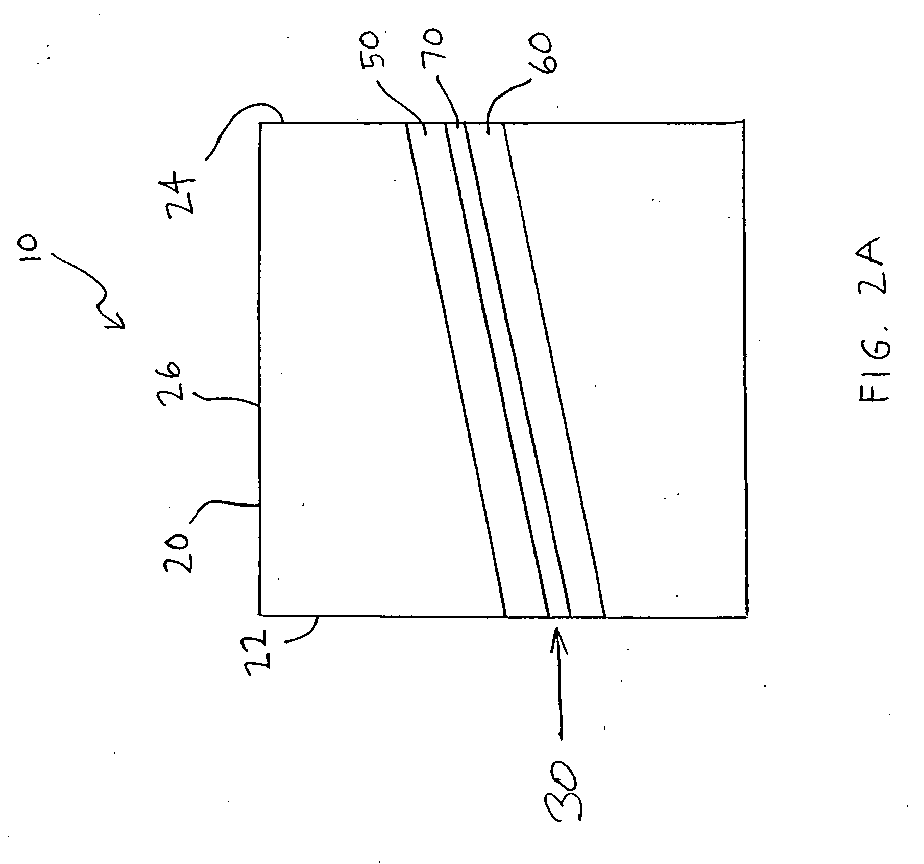
[0031]FIGS. 1 and 2 diagrammatically illustrate a cutting tool 10 according to one embodiment of the present invention. The cutting tool 10 is preferably a cutterhead that includes a body 20, which defines at least one cavity 30 (FIG. 3). Preferably there are multiple cavities 30 that are each at least generally uniform in shape along the length of the tool 10 and open at the circumferential surface and opposite ends of the tool 10. Knives 50, or other cutting instruments, and fillers 60 can be frictionally ...


PUM

PropertyMeasurementUnit
shear angleaaaaaaaaaa

Abstract

There is provided a rotatable cutting tool for supporting at least one knife in at least two alternate angular cutting configurations. The cutting tool includes a body that defines at least one cavity extending generally in a longitudinal direction of the body. Each cavity is configured to support one of the knives at predetermined hook and shear angles, and each cavity can be configured to provide a different hook and / or shear angle.

Description

CROSS-REFERENCE TO RELATED APPLICATION [0001] This application is a continuation-in-part of U.S. application Ser. No. 10 / 277,766, filed Oct. 22, 2002, which is hereby incorporated herein in its entirety by reference.BACKGROUND OF THE INVENTION [0002] 1) Field of the Invention [0003] The present invention relates to rotatable cutting tools and, more specifically, to supporting one or more knives in alternate configurations. [0004] 2) Description of Related Art [0005] Rotatable cutting tools are well known in the art and include, among others, saws, knives, cutterheads, heads or chucks with removable knives, drill bits, router bits, drills, end mills, moulders, and grinders of multiple shapes. These tools are used for cutting or grinding a variety of structural materials including, but not limited to, wood, metal, composite materials, plastic, foam, food products, and the like. [0006] One conventional rotatable cutting tool, commonly referred to as a cutterhead, typically includes a g...

Claims


Application Information

Patent Timeline
Patent Type & Authority Applications(United States)
IPC IPC(8): B27G13/04
CPCB27G13/04B26D7/2614Y10T83/04Y10T83/4824Y10T83/9464
Inventor RANKIN, DAVID DANIEL SR.
Owner MOLDER SERVICES
Why Eureka
Try Eureka