
Deceleration control apparatus and method for a vehicle

a control apparatus and vehicle technology, applied in the direction of braking systems, process and machine control, instruments, etc., can solve the problems of not meeting the deceleration torque produced by the brakes cannot match the deceleration torque produced by the automatic transmission, and the deceleration torque produced by the brakes cannot achieve good deceleration characteristics, etc., to achieve good deceleration transitional characteristics of the vehicle

Inactive Publication Date: 2005-06-09
TOYOTA JIDOSHA KK
View PDF19 Cites 51 Cited by
  • Summary
  • Abstract
  • Description
  • Claims
  • Application Information

AI Technical Summary

Benefits of technology

[0016] In view of the foregoing problems, this invention thus provides a deceleration control apparatus and method for a vehicle which can respond to various situations and achieve a good deceleration transitional characteristic for the vehicle.
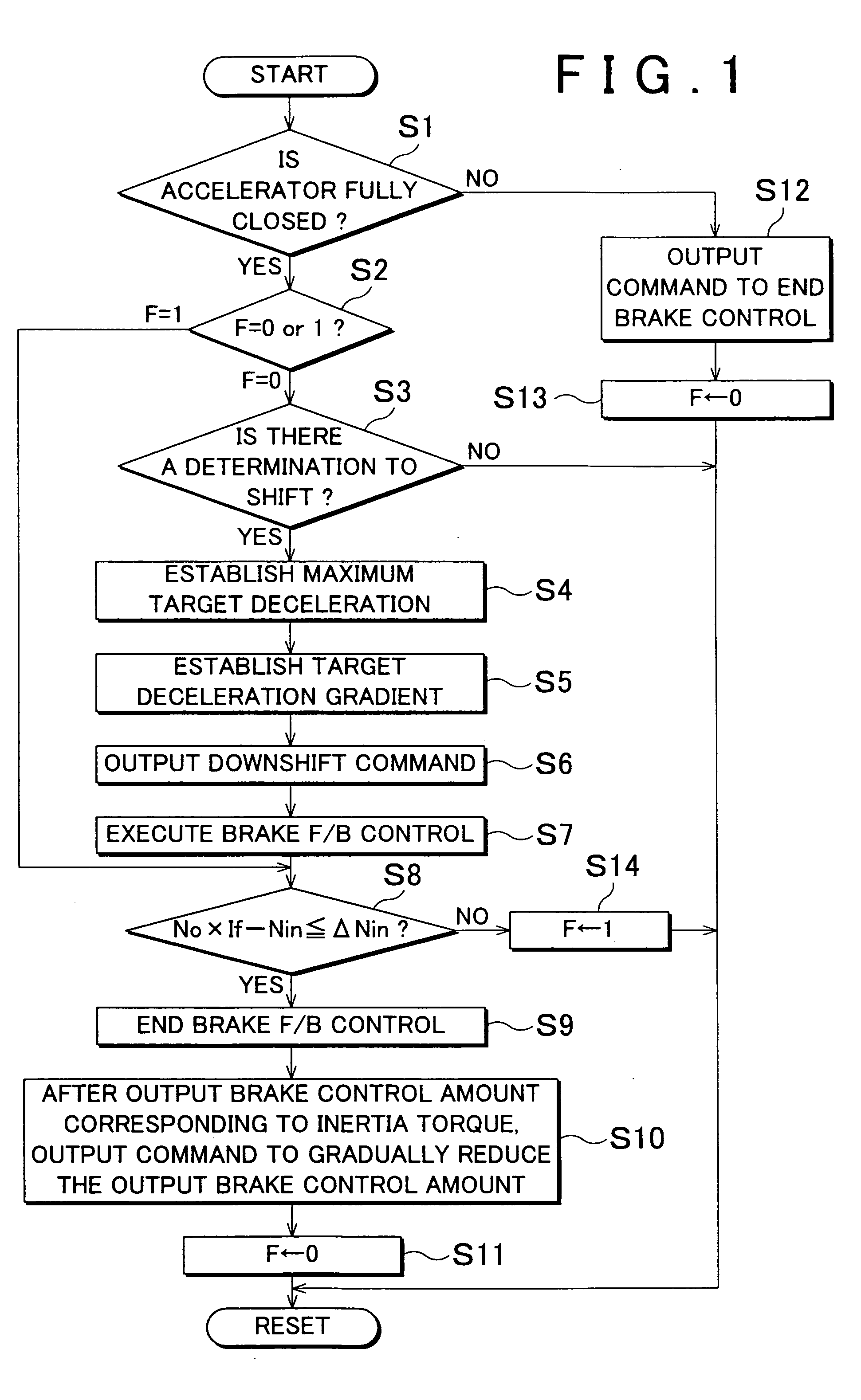
[0023] Unlike the control in U.S. Pat. No. 2,503,426, the control of this invention is not a sequence control (e.g., a control in which the stages of the control are proceeded through successively according to a predetermined sequence in which, after the type of shift is determined, the braking force is then determined based on that type of shift and the vehicle speed, and then that determined braking force is applied for a predetermined period of time). Therefore, this invention is able to respond to various situations, and as a result, achieve a good deceleration transitional characteristic of the vehicle.

Problems solved by technology

However, the following problems and complications arise when putting this method into practice.
That is, when the predetermined period of time is determined based on the detection results of the rotation speed of the output shaft of the automatic transmission and the like, detection delays, as well as a dispersion in those delays, may result in the deceleration torque produced by the brakes not matching the deceleration torque produced by the automatic transmission.
As a result, good deceleration characteristics may not be achieved.
Further, while it is possible to use a timer for timing the period of time that has passed from the shift timing (the start / end timing) when determining the predetermined period of time, dispersion in the shift timing may result in the deceleration torque produced by the brakes not matching the deceleration torque produced by the automatic transmission.
Also, with regard to the predetermined amount that the brakes are operated, dispersion (on both the release side and apply side) in the clutch torque of a clutch, which is an apply element of the automatic transmission, may also result in the deceleration torque produced by the brakes not matching the deceleration torque produced by the automatic transmission.
The foregoing problem arises due to the fact that both the automatic transmission and the brakes are sequence controlled in the foregoing publication.
Therefore, the technology in U.S. Pat. No. 2,503,426 does not anticipate flexibly controlling an event generated (by something other than a shift) in real time regarding a deceleration required by the vehicle by changing the braking force applied to the brakes.
Further, consideration given to the control details of the braking is insufficient.

Method used


Image

  • Deceleration control apparatus and method for a vehicle
  • Deceleration control apparatus and method for a vehicle
  • Deceleration control apparatus and method for a vehicle

Examples


Embodiment Construction

[0058] In the following description and the accompanying drawings, the present invention will be described in more detail with reference to exemplary embodiments.

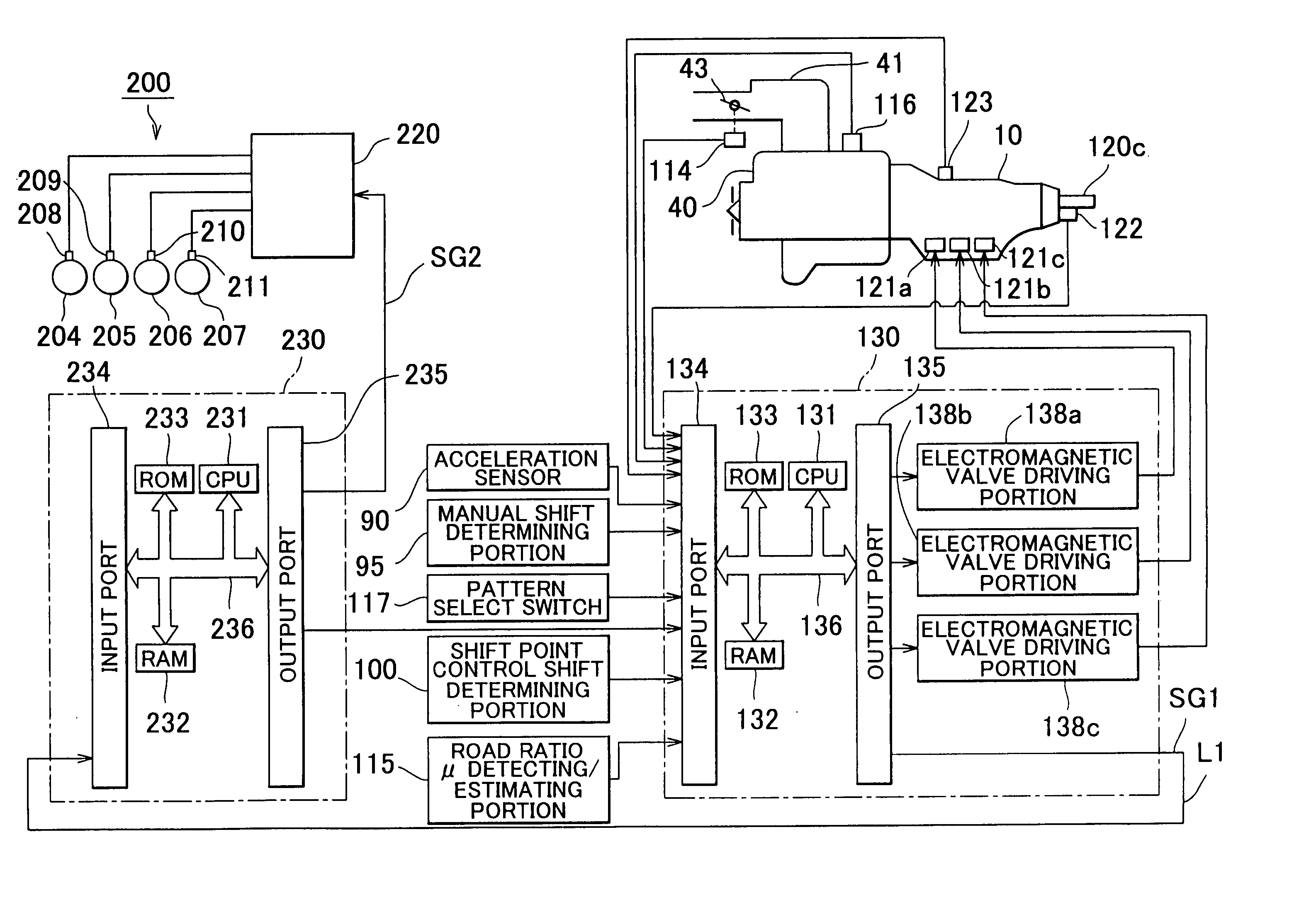
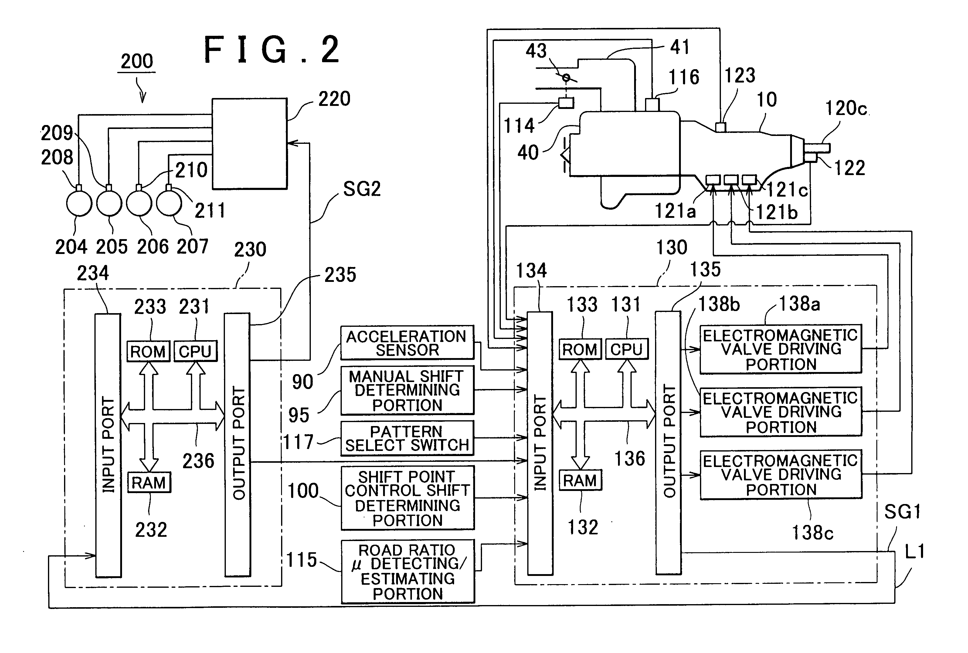
[0059] Hereinafter, ten embodiments according to the invention will be described. All ten embodiments relate to a deceleration control apparatus for a vehicle, which performs cooperative control of a brake system (including brakes and a motor / generator) and an automatic transmission. In addition, all ten embodiments have the following points in common.

[0060] That is, when a target value (a target deceleration) of a deceleration to be applied to the vehicle is set and a speed or speed ratio of the automatic transmission that is appropriate for achieving that target deceleration selected during cooperative control of the brake system and the automatic transmission, the brake system is controlled to compensate for the difference between the target deceleration and the deceleration produced by the shift into the selected spee...


PUM


Abstract

A deceleration control apparatus for a vehicle provided with a brake system for generating braking force in the vehicle, and a transmission, controls the brake system and the transmission such that a deceleration acting on the vehicle matches a target deceleration set as a deceleration to be applied to the vehicle by a brake operation of the brake system and a shift operation which shifts the transmission into a relatively low speed or speed ratio.

Description

INCORPORATION BY REFERENCE [0001] The disclosure of Japanese Patent Application No. 2003-407782 filed on Dec. 5, 2003 including the specification, drawings and abstract is incorporated herein by reference in its entirety. BACKGROUND OF THE INVENTION [0002] 1. Field of the Invention [0003] The invention relates to a deceleration control apparatus and method for a vehicle. More particularly, the invention relates to a deceleration control apparatus and method for a vehicle, which controls deceleration of the vehicle by an operation of a brake system which applies braking force to the vehicle and a shift operation that shifts an automatic transmission into a relatively lower speed or speed ratio. [0004] 2. Description of the Related Art [0005] Technology is known that controls an automatic transmission and a brake in cooperation by operating the brake when the automatic transmission is manually shifted into a speed that will cause the engine brake to engage. One such example of this ty...

Claims


Application Information

Patent Timeline
IPC IPC(8): B60K31/00B60T7/12B60T8/1755B60W10/10B60W10/11B60W10/115B60W10/18B60W10/188F02D29/02F16H61/02F16H61/21F16H61/68F16H61/684F16H61/686
CPCB60T8/1755B60T2270/613B60T2260/04B60W10/18F16H61/21B60W30/08
Inventor IWATSUKI, KUNHIROSHIIBA, KAZUYUKIFUJINAMI, HIROAKISEKI, MASATO
Owner TOYOTA JIDOSHA KK
Learn More