
Upshift control system of automatic transmission and method thereof

a control system and automatic transmission technology, applied in the field of automatic transmission, can solve the problems of deteriorating shift quality, affecting the reliability of automatic transmission, and affecting the accuracy of automatic transmission, and achieve the effect of reliable shift control

Inactive Publication Date: 2005-06-09
HYUNDAI MOTOR CO LTD
View PDF8 Cites 2 Cited by
  • Summary
  • Abstract
  • Description
  • Claims
  • Application Information

AI Technical Summary

Benefits of technology

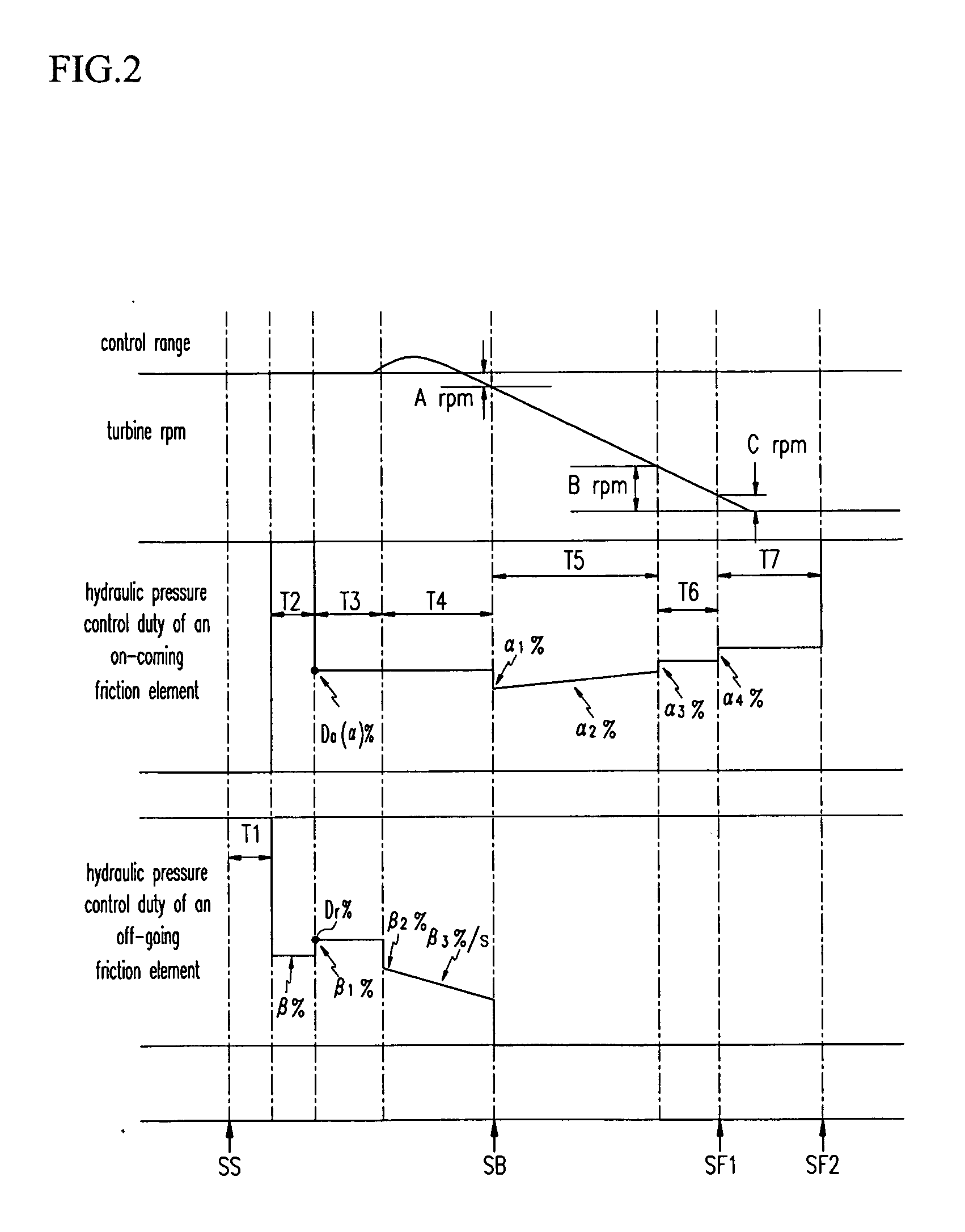
[0008] Embodiments of the present invention provide a shift control system and a method thereof for a power-on 2-3 upshift by controlling hydraulic pressure control duty of an off-going friction element according to an input torque and then completely releasing the hydraulic pressure from an off-going friction element at a point at which a current turbine rpm becomes lower than a second-speed synchronous turbine rpm by a predetermined value to achieve a reliable shift control.

Problems solved by technology

When the hydraulic pressure is released too quickly from the off-going friction element or when the hydraulic pressure is supplied too slowly to the on-coming friction element, a flare may occur such that shift quality may deteriorate.
Although an additional shift control scheme (e.g., a bang-bang control) can be used in order to solve such a problem, the shift feel may be deteriorated by torque changes due to the rapid increase of hydraulic pressure.
In particular, during a power-on 2-3 upshift, a flare phenomenon, in which turbine rpm abnormally increases according to hydraulic pressure states, may occur.

Method used


Image

  • Upshift control system of automatic transmission and method thereof
  • Upshift control system of automatic transmission and method thereof
  • Upshift control system of automatic transmission and method thereof

Examples


Embodiment Construction

[0021] Hereinafter, a preferred embodiment of the present invention will be described in detail with reference to the accompanying drawings.

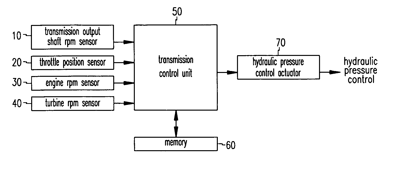
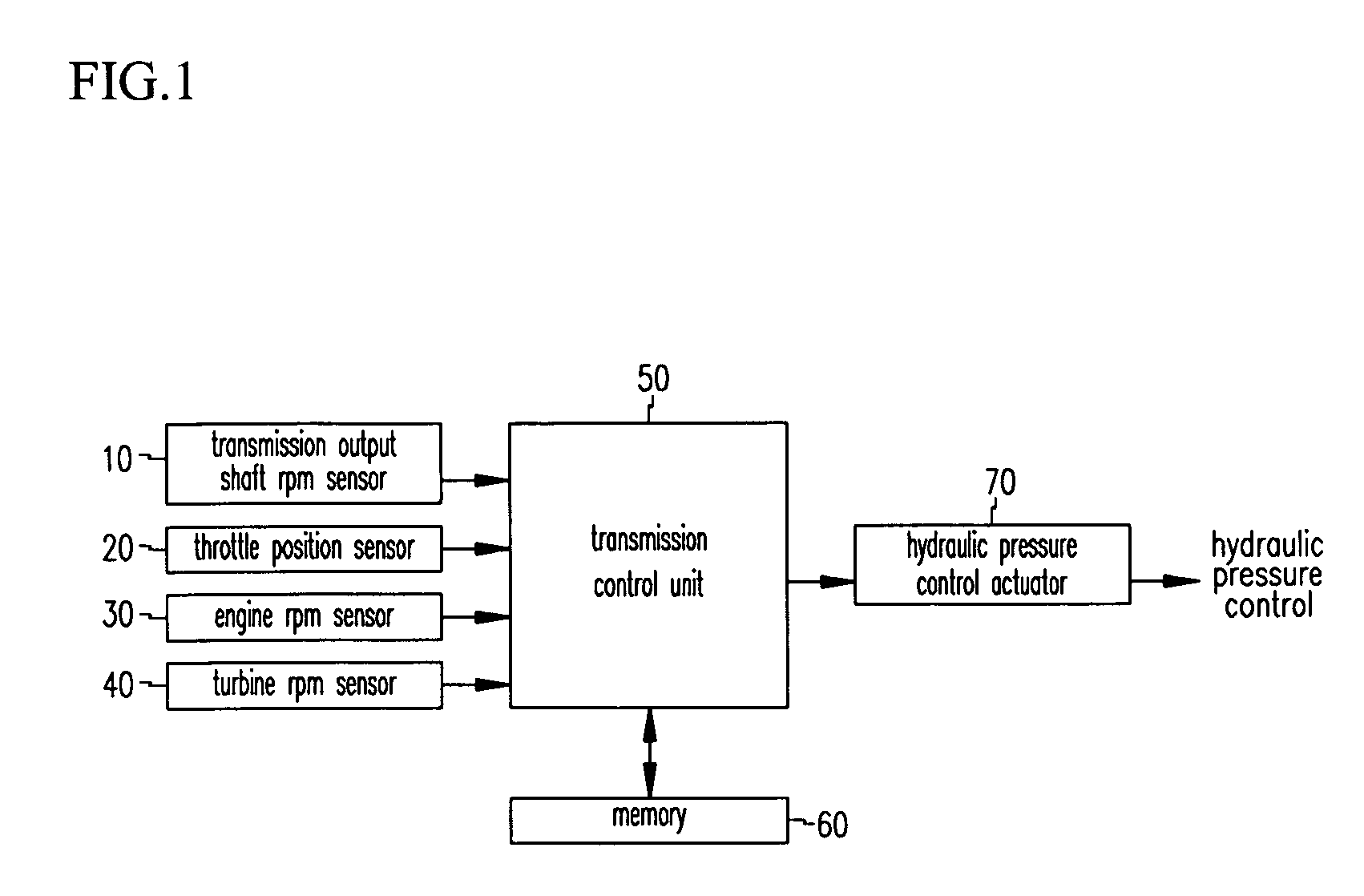
[0022] A hydraulic control apparatus according to an embodiment of the present invention, as shown in FIG. 1, comprises a transmission output shaft rpm sensor 10, a throttle position sensor 20, an engine rpm sensor 30, a turbine rpm sensor 40, a transmission control unit (TCU) 50, a memory 60, and a hydraulic pressure control actuator 70. The transmission output shaft rpm sensor 10 detects an output rpm of an automatic transmission output shaft and outputs a corresponding signal. The throttle position sensor 20 detects an opening angle of a throttle valve, which is operated by a depression of an accelerator pedal, and outputs a corresponding signal. The engine rpm sensor 30 detects an engine rpm and outputs a corresponding signal. The turbine rpm sensor 40 detects a turbine rpm and outputs a corresponding signal.

[0023] The TCU 50 may include a...


PUM


Abstract

A power-on 2-3 upshift control method for an automatic transmission comprises: determining whether a power-on 2-3 upshift condition exists; extracting an initial hydraulic pressure control duty and hydraulic pressure control duty depending on an input torque from a map table for an on-coming friction element and an off-going friction element, if it is determined that the power-on 2-3 upshift condition exists, and performing a shift control for the upshift; and completely releasing a hydraulic pressure of the off-going friction element at a point at which a hydraulic pressure for the on-coming friction element is capable of tolerating a turbine torque.

Description

CROSS REFERENCE TO RELATED APPLICATIONS [0001] This application claims priority of Korean Application No. 10-2003-0088011, filed on Dec. 5, 2003, the disclosure of which is incorporated herein by reference. TECHNICAL FIELD OF THE INVENTION [0002] The present invention relates to an automatic transmission, and more particularly, to an upshift control system and method for a power-on 2-3 upshift. BACKGROUND OF THE INVENTION [0003] Recent automatic transmissions often comply a clutch-to-clutch shifting system, i.e., an independent shifting system in which hydraulic control for an off-going clutch is not performed during an upshift or a downshift, and only release timing of the off-going clutch is controlled. Therefore, for the off-going clutch, after the release timing, the hydraulic pressure is released from the off-going friction element without additional control. [0004] In such a hydraulic control scheme, the timing of release of the hydraulic pressure from the off-going friction e...

Claims


Application Information

Patent Timeline
Patent Type & Authority Applications(United States)
IPC IPC(8): F16H59/24F16H61/06F16H59/38F16H59/40F16H59/42F16H59/46F16H59/68F16H61/04
CPCF16H61/061F16H2059/385Y10S477/904Y10T477/6895Y10T477/69383F16H2059/467F16H61/04
Inventor SHIM, HYUN SOO
Owner HYUNDAI MOTOR CO LTD
Learn More