
Quick release support post and associated method

a support post and quick release technology, applied in the direction of machine supports, threaded fasteners, screwdrivers, etc., can solve the problems of labor-intensive and time-consuming installation process, labor-intensive and time-consuming for the installer, and the difficulty of using tools and managing small parts, so as to reduce the time, labor, hardware and associated costs

Inactive Publication Date: 2005-06-09
THE BOEING CO
View PDF14 Cites 30 Cited by
  • Summary
  • Abstract
  • Description
  • Claims
  • Application Information

AI Technical Summary

Benefits of technology

[0009] In accordance with the present invention, a quick release support post, associated method, and quick release cable clamp are provided to attach cables to a structure and to facilitate later removal of the post or clamp, or a later move of the post or clamp to a different location without the need for many small parts and tools. Thus, cables, including wires, optical fibers and the like, may be installed in hard-to-reach areas quicker and easier than with conventional clamps because no tools are required and an installer generally does not have to use both hands. Furthermore, because the quick release support post, associated method, and quick release cable clamp of the present invention require only a hole in the structure for installation, there is no need for potting compound or steel inserts, and no extra weight is added to the structure during installation or movement. As such, it is less likely that a weight-sensitive existing structure must be redesigned when moving the quick release support posts or clamps of the present invention than when moving the conventional clamps. In addition, the quick release support posts and associated method of the present invention create efficient cable management systems because the cables may be grouped and secured to the support posts together, which makes trouble shooting and later moves much easier. Overall, the quick release support posts and associated method of the present invention save significant time, labor, hardware, and associated costs because they are more efficiently installed, moved and removed than conventional cable clamps.
[0013] The method for attaching a cable to a structure of the present invention includes providing an elongated rod having a varying cross-section in a longitudinal direction and an elongate sleeve capable of being axially translated along the rod, inserting a portion of the sleeve into a hole defined by the structure, translating the sleeve axially along the rod to facilitate positive engagement of the sleeve within the hole, and attaching at least one cable to the sleeve. The method also may include mounting the sleeve upon the rod in a first position prior to inserting a portion of the sleeve into the hole. In addition, translating the sleeve axially along the rod may include expanding the portion of the sleeve within the hole to positively engage the sleeve within the hole. Furthermore, attaching at least one cable to the sleeve may be accomplished by encircling the cable(s) and an attachment element that may be carried by the sleeve with a tie member.
[0014] Thus, the embodiments of the support post and associated method summarized above provide an efficient manner in which to secure cables to structures without requiring tools for installation or movement of the support post. Because of the shape and cooperation of the elongated rod and the sleeve, the sleeve is positively engaged within a hole to provide a base to which cables may be attached. In addition, because the quick release support post and associated method of the present invention do not require potting compound and / or a steel insert to install the clamps, but instead only require a properly sized hole in the structure, installing the support post is simple and does not add much extra weight to the structure. As such, the support posts may be moved to another location on the structure without concern over adding too much weight to weight-sensitive structures. Furthermore, the support post and associated method of the present invention provide efficient cable management because certain types of cables may be grouped together and kept separate from other cable types by securing the bundles to different attachment elements and / or different sleeves of the support post.
[0016] The cable clamp of the above embodiment also provides an efficient manner in which to clamp a cable with a clamp of a predetermined size without using tools or many small parts. In addition, this embodiment is easily moved to a different location on the structure because it also requires only a hole in the structure for installation. Therefore, all of the quick release cable clamp and associated method embodiments reduce the time, labor, hardware, and associated costs normally involved in cable clamp installation.

Problems solved by technology

Therefore, conventional cable bundle installation generally requires many pieces of loose hardware and tools to assemble the clamps.
Consequently, when installing cable bundles in tight areas, it is difficult to use the tools and manage the small parts.
Because of this difficulty and the multiple number of clamps that must be installed, the conventional installation process is labor-intensive and time consuming.
Therefore, when one clamp is in need of repair or removal, several other clamps will first require removal with tools before enough space is created to reach the cable bundle clamp requiring attention, which is also labor-intensive and time-consuming for the installer.
In addition, when stacking clamps of this type, cable management is difficult because there is no way to ensure that certain types of cables, such as those for the electrical systems, are grouped together.
Without cable management, trouble shooting and movement of only certain systems and their associated cables is difficult.
Furthermore, a slight change in the location of a component of a system may require the cable bundle routes to change, which, at the least, requires a significant amount of time and labor to remove the clamp fasteners and clamps with tools and reinstall them in the new location.
In some cases, the structural designers / engineers may have to revise the structure to accommodate the new cable bundle attachments due to the space required and structural support needed for installation.
Thus, because new holes must be drilled and new potting compound and / or steel insert applied, the existing structure may not be able to withstand the extra weight.
In addition, the structural panels cannot provide a grid of inserts to allow for many possible cable bundle installations because of the excessive weight of the inserts and the prohibitive expense of the labor involved in the tedious process of preparing for attachment that may not be utilized.
While this clamping technique is useful because it eliminates the need for tools, potting compound, and steel inserts, the strap feature with many holes along one end does not provide a strong enough clamp for cables in many applications that are subjected to relatively large forces, such as frequent movements and vibrations.
Thus, the strap is more likely to break.
In addition, because there is no way to cinch the strap securely around the cables since the locations of the holes in the strap are predetermined, then the cables may be loose in the strap, which could cause the strap to rub against the cables and damage the cables such that the systems supported by the cables may become inoperable.
Furthermore, the straps may not be stacked due to the short length of the pin.

Method used


Image

  • Quick release support post and associated method
  • Quick release support post and associated method
  • Quick release support post and associated method

Examples


Embodiment Construction

[0026] The present invention now will be described more fully hereinafter with reference to the accompanying drawings, in which preferred embodiments of the invention are shown. This invention may, however, be embodied in many different forms and should not be construed as limited to the embodiments set forth herein; rather, these embodiments are provided so that this disclosure will be thorough and complete, and will fully convey the scope of the invention to those skilled in the art. Like numbers refer to like elements throughout.

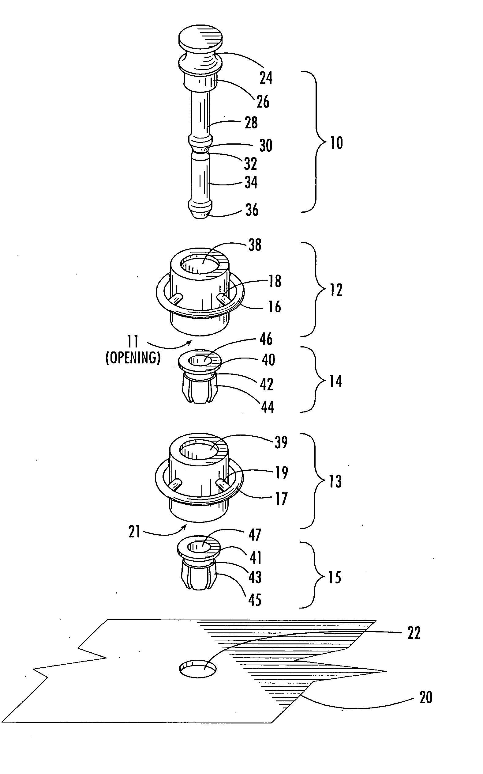
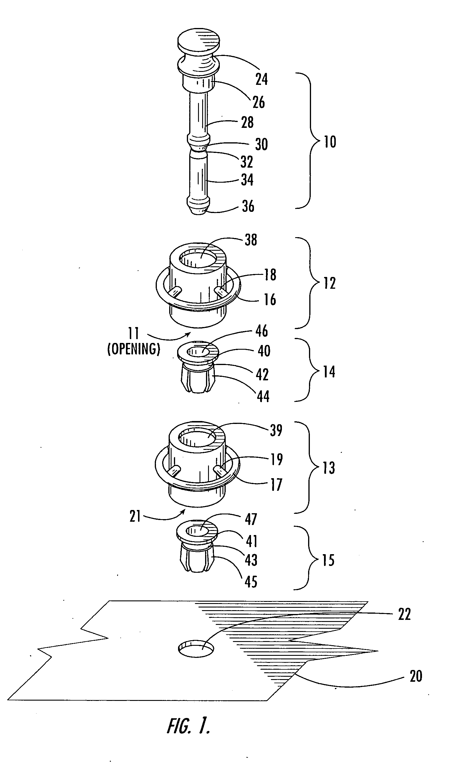
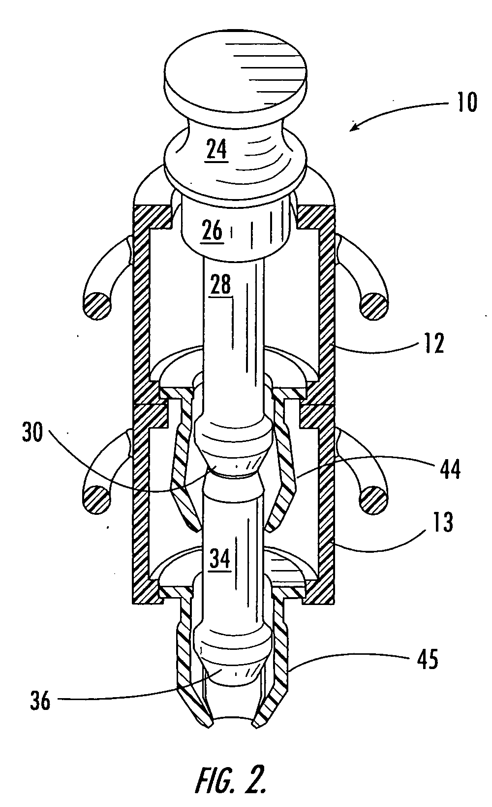
[0027] The quick release support post of the present invention includes an elongated rod and an elongated sleeve mounted on the rod. The sleeve may include an expandable engagement member, such as an expanding rivet-like feature, near one end, such as at the base of the sleeve. In addition, at least one attachment element, such as a ring, may be carried by the sleeve, such as being longitudinally centrally located on the sleeve. The attachment element, s...


PUM


Abstract

A quick release support post and associated method are provided to attach a cable to a structure and later move the cable location without the need for many small parts and tools. Thus, cables and wires may be installed in hard-to-reach areas quicker and easier than with conventional clamps because no tools are required and an installer generally does not have to use both hands. Because the quick release support posts and associated method require only a hole in the structure for installation, there is no need for extra materials, and minimal weight is added to the structure during installation or movement. In addition, the quick release support posts and associated method of the present invention create efficient cable management systems because the support posts may be various lengths and cables may be grouped and secured to the support posts together, which makes trouble shooting and later moves much easier.

Description

FIELD OF THE INVENTION [0001] The present invention relates to securing cables to structures, and more particularly to quick release support posts that facilitate in cable installation, post-installation movement, and cable management. BACKGROUND OF THE INVENTION [0002] Modern vehicles and other structures utilize many systems, such as lighting and electronics, that have various separate components. For example, the systems may have dedicated components, such as receptacles, controls and / or displays, and shared components, such as power supplies and processors. The components may be located remotely from each other, which necessitates cables, including wires, to connect the components for the systems to function properly. Thus, the cables may span a considerable length depending upon the locations of the components relative to one another. It is typically desirable to enclose the cables in tubes, such as raceways, that extend along a relatively secluded area of the vehicle or struct...

Claims


Application Information

Patent Timeline
Patent Type & Authority Applications(United States)
IPC IPC(8): F16B5/06F16B19/10
CPCF16B5/0685Y10T24/309Y10T24/42F16B19/1081
Inventor SLYTER, KENNETH M.
Owner THE BOEING CO
Learn More