
Spray booth systems and methods for accelerating curing times

a technology of spray booths and curing times, applied in the field of spray booths, can solve the problem of taking up to 40 minutes for the entire vehicle, and achieve the effect of increasing the evaporation rate, increasing the air flow locally, and not substantially increasing the pressure within the interior

Active Publication Date: 2005-06-09
GARMAT USA LLC
View PDF35 Cites 19 Cited by
  • Summary
  • Abstract
  • Description
  • Claims
  • Application Information

AI Technical Summary

Benefits of technology

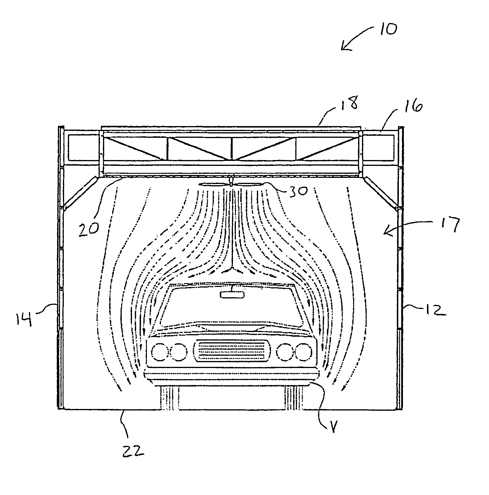
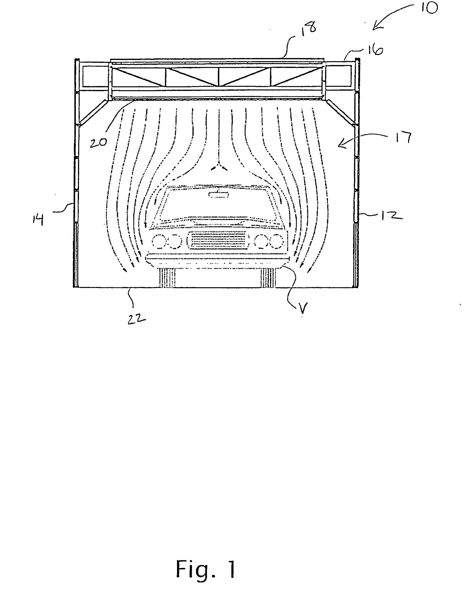
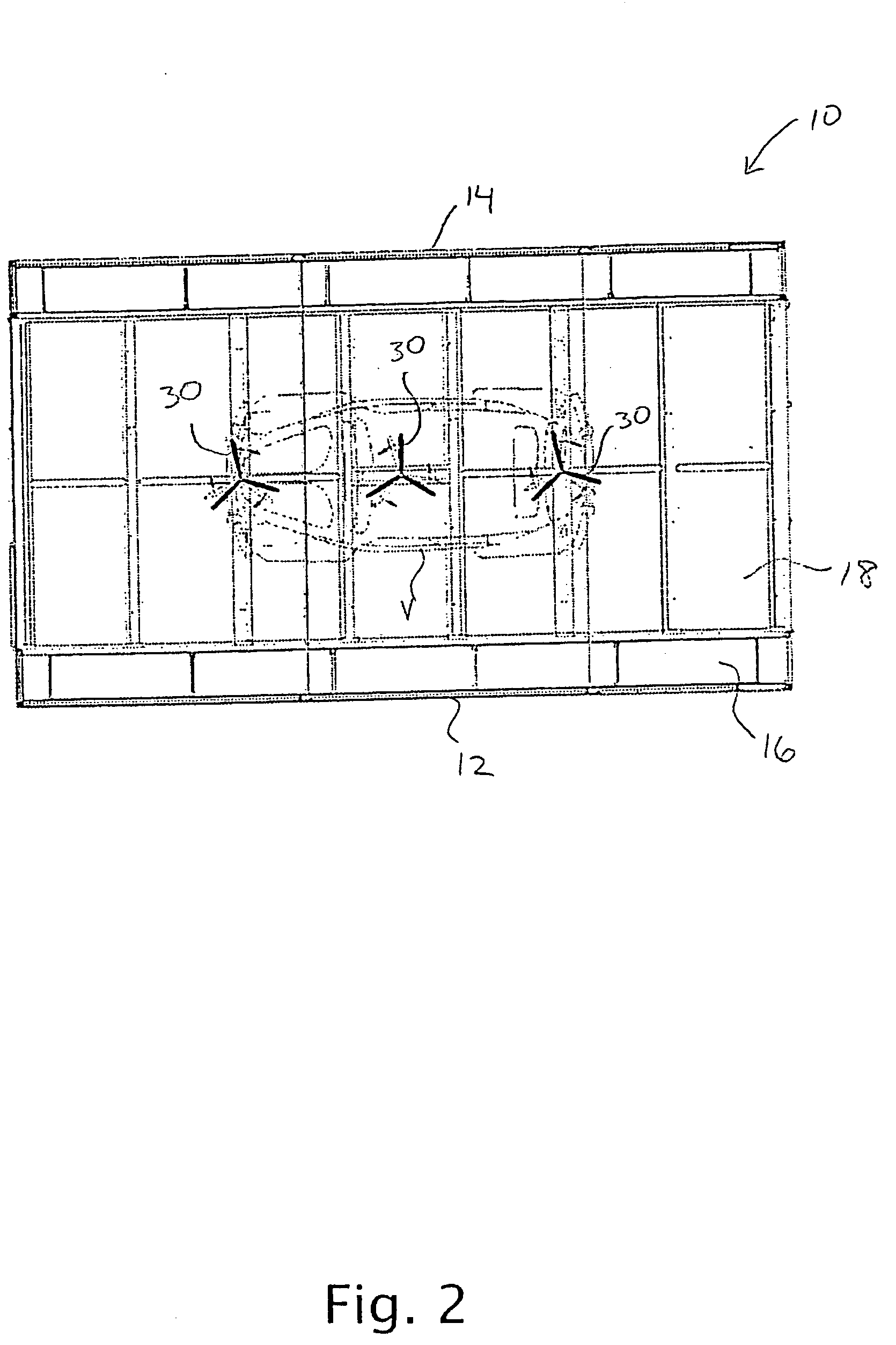
[0006] One embodiment of the invention provides a spray booth that comprises a spray booth housing having a ceiling and side walls that define an interior for holding an object to be sprayed. A pressurized air plenum is disposed above the ceiling and is adapted to supply air into the interior. A filter media is used to filter air from the plenum before entering into the interior. At least one fan is disposed in the interior below the filter media. The fan is operable to locally increase air flows in the vicinity of the object to increase evaporation rates associated with a spray application on the object, and to enhance air flow over the object during a spray, dry and cure cycle. In this way, enhanced airflows over the object may be achieved without increasing air flows through the plenum. As such drying times may be significantly reduced.
[0012] One particular advantage is that the air flows are locally increased within the interior without substantially increasing the pressure within the interior. In this way, the flow within the plenum does not need to be increased to increase evaporation rates. In one aspect, the spray application comprises a waterborne paint, and the increased air flows enhance the evaporation of water from a surface of the waterborne paint. The techniques of the method may be used in essentially any type of spray booth having a downdraft flow or a semi-vertical flow.

Problems solved by technology

Even at elevated temperatures and a down draft of semi-vertical draft, it can take up to 40 minutes for the entire vehicle to dry sufficiently to permit removal from the spray booth.

Method used


Image

  • Spray booth systems and methods for accelerating curing times
  • Spray booth systems and methods for accelerating curing times
  • Spray booth systems and methods for accelerating curing times

Examples


example

[0029] One non-limiting example of how the techniques of the invention may be used to increasing drying and curing times is set forth below. The example utilized a Garmat USA, Inc. PPG Envirobase Waterborne Base with DC3000 High Velocity Clearcoat. The spray booth was a Garmat USA, Inc. 3000 series paint spray booth (available from Garmat USA, Inc.) fitted with the three 24 inch diameter aluminum blade propeller fans similar to the embodiment in FIGS. 2-4.

[0030] The booth was set to 72 F. and 0.02″ W.C. A 2002 Buick Century was used for the test. The first coat of base was applied medium wet with the timing beginning as soon as the spraying began. The roof of the car was sprayed. The waterborne base coat completely flashed off in 5.46 minutes without the use of the propeller fans.

[0031] The second coat of base was applied, medium wet, and the three fans were rotated during spraying at about 750 rpm, and raised to about 1050 rpm for the dry phase. The waterborne base completely fla...


PUM

PropertyMeasurementUnit
diameteraaaaaaaaaa
speedaaaaaaaaaa
air flow ratesaaaaaaaaaa

Abstract

One embodiment of the invention provides a spray booth that comprises a spray booth housing having a ceiling and side walls that define an interior for holding an object to be sprayed. A pressurized air plenum is disposed above the ceiling and is adapted to supply air into the interior. A filter media is used to filter air from the plenum before entering into the interior. At least one fan is disposed in the interior below the filter media. The fan is operable to locally increase air flows in the vicinity of the object to increase evaporation rates associated with a spray application on the object, and to enhance air flow over the object during a dry or a cure cycle.

Description

CROSS REFERENCES TO RELATED APPLICATIONS [0001] This application is a nonprovisional application which claims the benefit of U.S. Provisional Application Nos. 60 / 530,780, filed Dec. 17, 2003, and 60 / 526,924, filed Dec. 3, 2003, the complete disclosures of which are herein incorporated by reference.BACKGROUND OF THE INVENTION [0002] This invention relates generally to the field of spray booths, and in particular to spray booths where air is flowed from the ceiling and past the object being sprayed. More specifically, the invention relates to increasing air flow rates around an object being sprayed to increase evaporation rates. [0003] When painting a vehicle or other object, drying or curing times can limit the amount of throughput. One common way to spray a vehicle is by using a spray booth. These booths provide advantages such as reducing particulate, confining paint overspray and evaporated solvents, and reducing drying times. To accelerate drying, air is flowed through the booth ...

Claims


Application Information

Patent Timeline
Patent Type & Authority Applications(United States)
IPC IPC(8): B05B15/12F26B21/00F26B21/02F26B21/12F26B25/10
CPCB05B15/1207B05B15/1222F26B21/003Y10S118/07F26B21/12F26B25/10F26B2210/12F26B21/02B05B16/20B05B16/60
Inventor DEREGGE, KAREL
Owner GARMAT USA LLC
Learn More