
Custom prosthetic liner manufacturing system and method

Active Publication Date: 2005-06-02
WILLOWWOOD GLOBAL LLC
View PDF24 Cites 75 Cited by
  • Summary
  • Abstract
  • Description
  • Claims
  • Application Information

AI Technical Summary

Benefits of technology

[0005] AK prosthetic legs will also generally have an upper, socket portion, that is provided to receive a portion of the amputee's residual limb. An AK prosthetic limb will also typically have a lower portion attached to the bottom of the socket. Normally, the lower portion of an AK prosthetic limb will also have an upright assembly of some type that is connected to a foot or ground-contacting portion. Older AK prosthetic limbs sometimes incorporated a rudimentary type of pivoting assembly to connect the lower portion to the socket. This allowed the amputee to swing the lower portion of the prosthetic limb forward during walking, in an attempt to simulate the amputee's natural gait. Modern AK prosthetic limbs are typically more complicated. For example, hydraulic or pneumatic cylinders, or some other type of damping device may be provided at the knee joint to better control the bending thereof.
[0015] The Applicant currently manufactures and sells a liner that is substantially superior to those liners discussed above. The Applicant's current liner, known commercially as the Alpha® liner, is available to amputees as an off-the-shelf product. This liner is generally manufactured from a novel block copolymer material to which is adhered a fabric covering. The fabric-covered liner is easily rolled onto the residual leg or arm, with the fabric material facing out. The fabric material allows for easy donning and doffing of a prosthetic limb, as the inner surface of the prosthetic limb socket slides easily over the fabric. The fabric material also improves the durability, stability, and cosmetic appearance of the liner. In comparison to the aforementioned liners, the Applicant's existing liner is generally longer, with the block copolymer material typically extending substantially to the edge of the fabric that typically extends beyond the brim of the socket. The design of the Applicant's existing liner offers superior cushioning, better prevents air entry, and reduces the chances of perspiration forming around the portion of the residual limb that resides within the prosthetic limb socket. Also, the particular block copolymer material used allows the liner to better conform to the shape of the amputee's residual limb, and may contain additives, such as mineral oil, which act to condition the skin.
[0016] In a similar manner to the aforementioned and previously known liners, however, the Applicant's present liner has been heretofore available in only a few standard sizes. Thus, an amputee has up until now been required to order an Alpha® liner of a size that most closely approximates the size of their residual limb. Due to its design and construction, such an off-the-shelf Alphas liner still typically provides for a comfortable fit—and is still generally superior to previous liners. This is due in part to the ability of the Alpha® liner to conform to the shape of an amputee's residual limb as the liner is worn. However, the ability to manufacture such a liner that is also customized to fit an individual amputee remains desirable, as such a custom liner would provide for an even further improvement in fit, and may be especially beneficial to amputees who have, for example, highly sensitive, bony, or unusually shaped residual limbs.
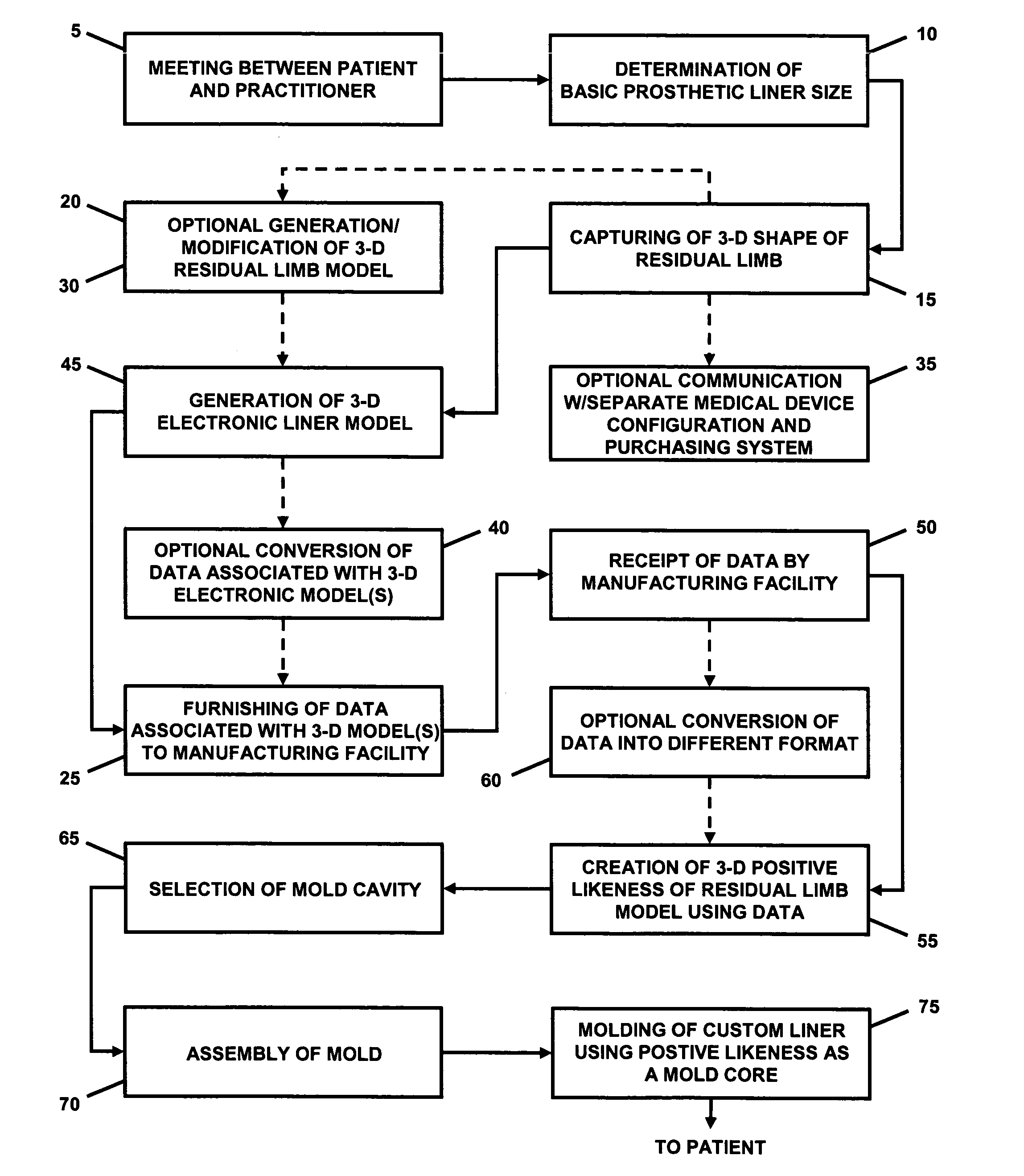
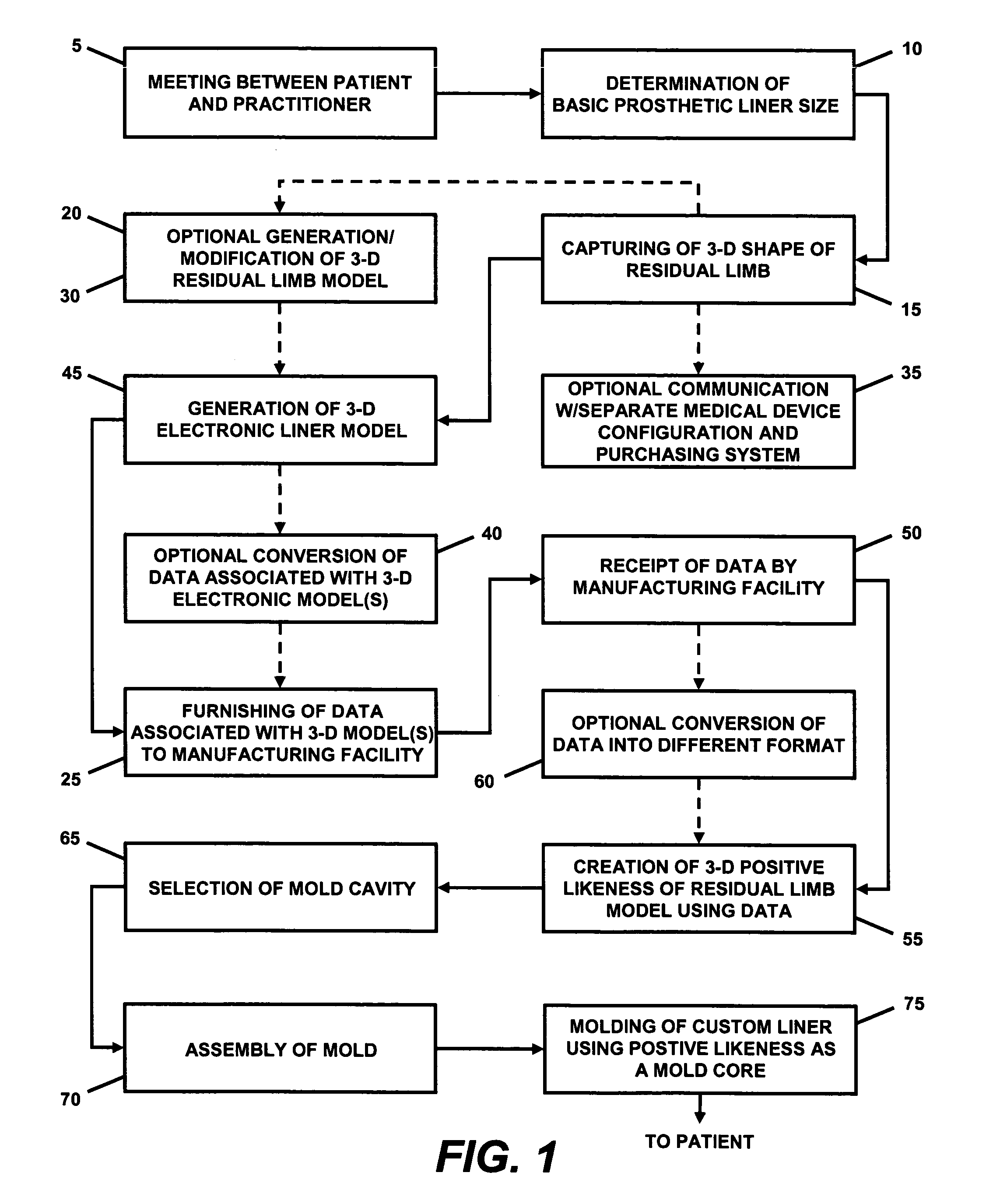
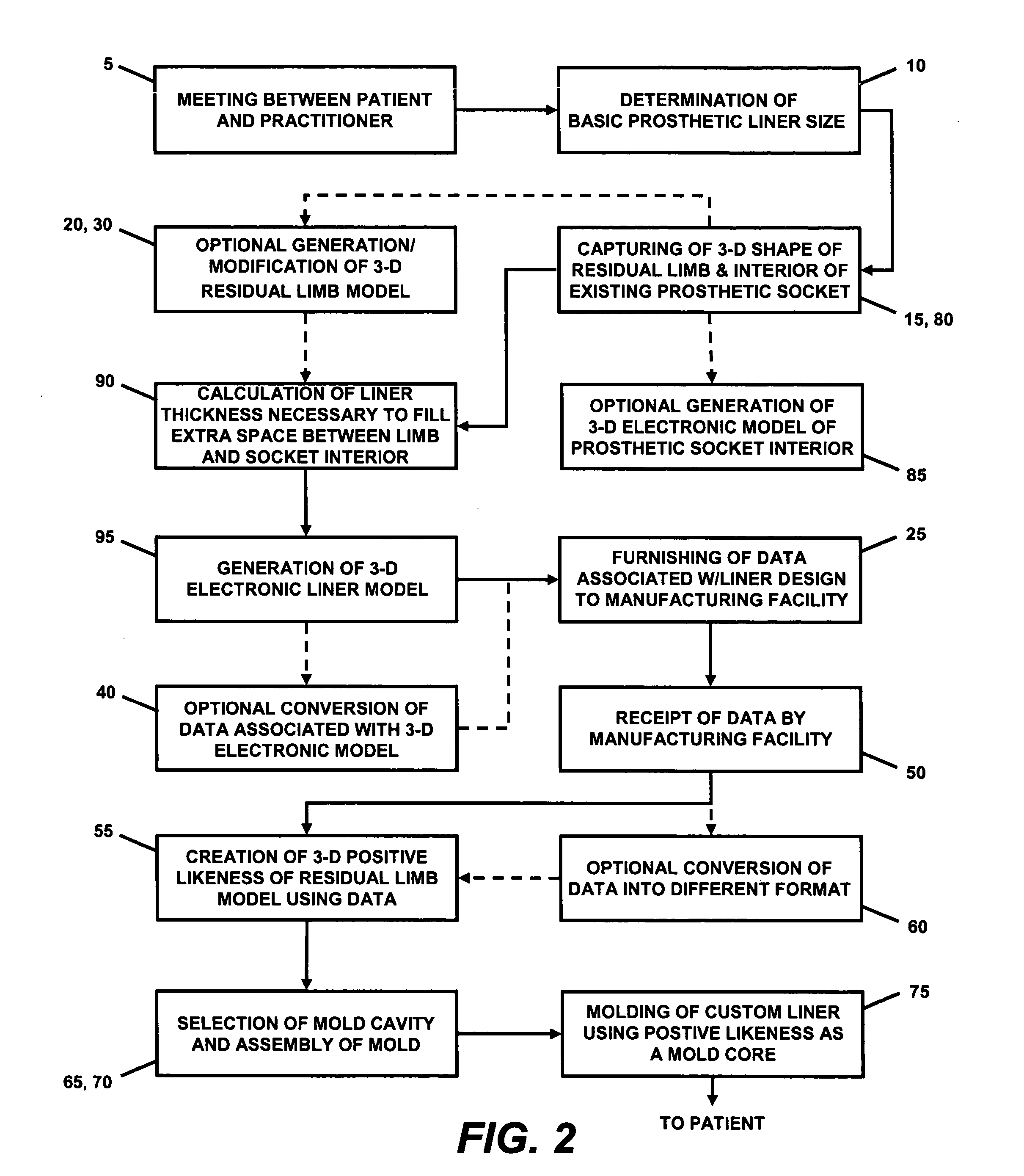
[0018] The system and method of the present invention overcomes the aforementioned problems and allows the manufacture of a custom prosthetic liner of any type (i.e., leg, arm, etc.) in a timely and cost efficient manner. The system and method of the present invention eliminates the need to cast an amputee's residual limb in order to obtain the accurate shape thereof. Rather, one embodiment of the system and method of the present invention can obtain the accurate shape of an amputee's residual limb by making use of a shape capture device to capture the 3-dimensional shape of the residual limb with a high degree of accuracy, or through the application of measurements to a shape template. Software associated with the shape capture device may optionally be used to convert the 3-dimensional shape (image) into a 3-dimensional electronic model that accurately represents the residual limb. Alternatively, the software associated with the shape capture, or other software, can apply measurements to a shape template to produce a 3-dimensional electronic model that represents the residual limb. The software, through an interface, preferably also allows a prosthetist or other qualified practitioner to produce a 3-dimensional electronic model of a liner that makes use of the exterior shape of the residual limb to calculate its interior geometry. The liner model can be generated regardless of whether a residual limb model has been generated. If used, the practitioner can modify the residual limb model in order to further fine-tune the fit of the liner that will be produced therefrom. Once the liner model is deemed to be in acceptable form, the data associated therewith is transmitted or otherwise provided to a manufacturing facility that is equipped to receive the data and to produce a liner therefrom. In one embodiment of the present invention, the data is used to produce a 3-dimensional positive likeness of the (modified or unmodified) residual limb from a selected material. The 3-dimensional positive likeness of the residual limb can then be used as a mold core in conjunction with a standard (existing) liner mold cavity to produce a custom prosthetic liner. Thus, this embodiment of the system and method of the present invention does not require the use of a wholly unique liner mold in order to produce the custom liner. In another embodiment of the present invention, the data may be used to produce unique positive (core) and negative (cavity) portions of a liner mold. In this embodiment of the present invention, the whole of each mold is then unique to a particular amputee. While this method is likely more costly than the previously described method, it is contemplated that such molds could be manufactured of low cost materials, as such molds are not likely to experience a high number of molding cycles.
[0020] In any event, the system and method of the present invention allows an amputee to easily acquire a prosthetic liner that is customized to fit his / her residual limb, thereby providing for maximum comfort and support. Further, the first and subsequent custom liners can be ordered from the manufacturer(s) in the same manner as other prosthetic supplies, and can be delivered to the amputee in a timely manner and at a reasonable price. The system and method of the present invention also makes the storage of residual limb casts or molds optional, as the data required to produce the liner can be stored in electronic form. The system and method of the present invention may further permit a prosthetist or other qualified practitioner to specify options for inclusion on the liner, such as, for example: different types of suspension components and their size, location and orientation; bladders (including inflatable bladders) and their location and size; liner materials and material properties, including hardness, elasticity; the inclusion of additives, such as anti-microbials, therein; liner cover properties; and, sensors and their type and location. Additionally, the system and method of the present invention may allow for the manufacture of a custom liner that permits an amputee whose residual limb size / shape has changed, to continue using his / her existing socket. Similarly, it may be possible to produce custom liners that allow amputees to use a generic socket, with the difference in shape being accounted for by the liner, thereby greatly reducing the overall cost of a prosthetic limb. Therefore, as can be seen from the foregoing discussion, and as can be even better understood from a reading of the following detailed description of exemplary embodiments, the system and method of the present invention permits the practical manufacture of a custom prosthetic liner that has not been heretofore possible.

Problems solved by technology

Modern AK prosthetic limbs are typically more complicated.
No matter how well the prosthetic leg is otherwise designed, if the fit of the residual leg within the socket is not adequate, the prosthetic leg may irritate the residual leg, cause pain to the amputee, and / or may not be adequately retained.
Thus, without a proper fit of the residual leg to the socket, a prosthetic leg can be substantially unusable.
There are numerous problems with a skin fit, however.
Most notably, the constant contact of the skin against the hard inside surface of the socket can become painful, and can also cause problems with the skin of the residual leg.
This problem may be exacerbated when the residual leg has little flesh, or exhibits particularly bony areas.
Also, the skin of the residual leg may become irritated, chapped or raw, or may otherwise develop sore spots, lesions, or similar areas of weakness due to its contact with the socket.
A skin fit may also cause the residual leg to perspire, jeopardizing the seal between the residual leg and socket, and further contributing to problems with the amputee's skin.
Such surface modifiers are not only messy, they may be uncomfortable, and may further contribute to problems with the skin of the residual leg.
Such socks were problematic, however, particularly because they often lacked adequate comfort and secure suspension.
As can be imagined, this process is cumbersome, messy, and likely produces a liner of substantially less than uniform thickness.
In addition, a liner produced using this kit was required to be attached to a prosthetic leg via a pin connection, as a suction fit between the liner and the socket was not attainable.
Unfortunately, because the residual leg can be of virtually unlimited size and shape, it was often difficult to select a liner that fit acceptably.
The gel sock was very thin and offered no means of suspension.
Another substantial disadvantage of the gel sock was that it commonly caused adverse reactions of an amputee's skin when worn.
Unfortunately, this urethane liner had problems of its own.
Because the manufacturing process associated with this liner is relatively slow, it often took weeks to receive the liner after sending out the cast or mold.
A further drawback associated with this liner and liner manufacturing method is the fact that the liner manufacturer must keep a positive mold of the amputee's residual leg if additional liners are to be made for that amputee in the future.
As the typical mold was made from plaster, such molds are generally, fragile, and take up a not insubstantial amount of space.
Yet another drawback was that this system was not compatible with a pin suspension.
In fact, to the best of the Applicant's knowledge, no form of liner was available for use with AK prosthetics until approximately the mid-1990's, and the use of liners with AK prostheses employing suction retention did not gain acceptance until approximately 2001.
For certain of the reasons described above with respect to known prosthetic liners, as well as for other reasons, it has up until now been impractical to produce a custom liner.
In addition, it would be extremely cost prohibitive to manufacture a liner mold designed specifically to account for the peculiarities of each amputee's residual limb.
While this method is likely more costly than the previously described method, it is contemplated that such molds could be manufactured of low cost materials, as such molds are not likely to experience a high number of molding cycles.

Method used


Image

  • Custom prosthetic liner manufacturing system and method
  • Custom prosthetic liner manufacturing system and method
  • Custom prosthetic liner manufacturing system and method

Examples


Embodiment Construction

)

[0026] The system and method of the present invention allows for the efficient and cost effective manufacturing of a custom prosthetic liner. The system and method of the present invention will generally include: a means for scanning, photographing, digitizing, measuring, or otherwise capturing the 3-dimensional shape of an amputee's residual limb; an optional means for converting the captured shape of the residual limb into a viewable 3-dimensional model; a means for producing a viewable 3-dimensional liner model; a means for manipulating the 3-dimensional residual limb and / or liner model in order to further enhance and customize the fit and performance of the liner that will be manufactured therefrom; a means for providing the finalized data associated with the 3-dimensional liner model to a facility that will manufacture a liner from the data; a means for producing a 3-dimensional likeness (positive) of the (modified or unmodified) residual limb from the data; and a means of usi...


PUM


Abstract

A system and method for manufacturing a custom prosthetic liner. The system may include a shape capture device for capturing the shape of a residual limb. The captured shape may be used to generate a 3-dimensional electronic liner model using a processor and specialized software. A 3-dimensional electronic model of the residual limb may also be produced. Preferably, an interface is provided that allows a user of the system to alter the shape and / or size of the 3-dimensional model(s) to allow the subsequently-produced liner to accommodate particular features of the residual limb. Data associated with at least the resulting 3-dimensional liner model is provided to a manufacturing facility equipped to produce a custom liner therefrom. The data may be remotely transmitted to the manufacturing facility. A positive likeness of the residual limb is created from the data associated with the 3-dimensional model(s), and is subsequently used as a mold core in the liner molding process.

Description

BACKGROUND AND SUMMARY OF THE INVENTION [0001] The present invention relates to the production / manufacturing of custom liners for use with prosthetic limbs of various type. More specifically, the present invention relates to a system and method of manufacturing custom prosthetic liners, whereby a prosthetist or other qualified practitioner can capture the shape of an amputee's residual limb, manipulate data relating to said shape, if desired, and transmit or otherwise provide said data to a manufacturing facility that is equipped to receive the data and to manufacture a custom prosthetic liner therefrom. [0002] While there are various types of prosthetic limbs, the most common are likely those designed to replace some portion of an arm or leg. While a liner manufactured by the system and method of the present invention will work equally well in either application, for purposes of simplicity, we will confine the immediately following discussion of the present invention and relevant k...

Claims


Application Information

Patent Timeline
IPC IPC(8): A61B5/103A61B5/107A61F2/50A61F2/60A61F2/78G06FG06F1/00G06F19/00
CPCA61B5/0064A61B5/1073A61B5/1077A61F2/5046A61F2/7812A61F2002/5047Y10S623/901A61F2002/5053A61F2002/607A61F2002/608A61F2002/7831G05B2219/45168A61F2002/505
Inventor ARBOGAST, ROBERT E.COLVIN, JAMES M.KELLEY, CHRISTOPHER T.PRATT, GREG
Owner WILLOWWOOD GLOBAL LLC
Learn More