
Catheter navigation within an MR imaging device

Inactive Publication Date: 2005-06-02
UNIV OF VIRGINIA ALUMNI PATENTS FOUND
View PDF88 Cites 92 Cited by
  • Summary
  • Abstract
  • Description
  • Claims
  • Application Information

AI Technical Summary

Benefits of technology

[0016] In some modern MRI machines, the patient can actually be rotated during a procedure relative to a transverse MRI magnetic field residing in a gap between magnets. Such patient rotations may be employed to further enhance navigation. In particular, the patient may be rotated in these machines to ensure that maximum torque can always be applied about directions that would otherwise be parallel with the MRI field.

Problems solved by technology

Four inherent limitations to this general design of magnetic stereotaxis system are the following.
First, it is generally unsafe to perform magnetic resonance (MR) imaging studies during or after a magnetic stereotaxis procedures in which the magnetic element of the implant is still resident within the patient, as might be contemplated in situations where updated MR data might be needed for ongoing magnetic stereotaxis navigation requirements.
This is because the large fields intrinsic to all types of MR scanners (either standard bore-type systems or the lower-field interventional-style systems) are large enough to cause otherwise uncontrolled displacement of the implant within the patient.
A second limitation of the existing art is that relatively complex arrangements of magnetic field sources external to the patient must be assembled and controlled in order to carry out magnetic stereotactic movement of the implant.
A single static background field is virtually always inappropriate for effecting controlled movement of the magnetic element in the implant used in existing magnetic stereotaxis procedures.
A third limitation, related to the second, is that a magnetic element left in the brain or another body part can create a significant imaging artifact when that body part is imaged by an MR scanner, most typically rendering that imaging data set useless or of greatly reduced diagnostic and therapeutic value to the clinician and patient.
A fourth limitation is that appreciably and clinically precious time could be lost when carrying out a sequential and reciprocal process of conducting a magnetic stereotaxis procedure that must be interleaved with intra-operative MR imaging studies for diagnostic, therapeutic or navigational purposes.
Instead, such coil systems have been limited in function to identifying the location of the probe (in which they are housed) in relation to the body part into which the probe is inserted.

Method used


Image

  • Catheter navigation within an MR imaging device
  • Catheter navigation within an MR imaging device
  • Catheter navigation within an MR imaging device

Examples


Embodiment Construction

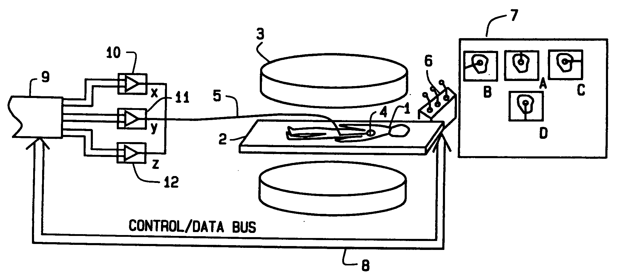
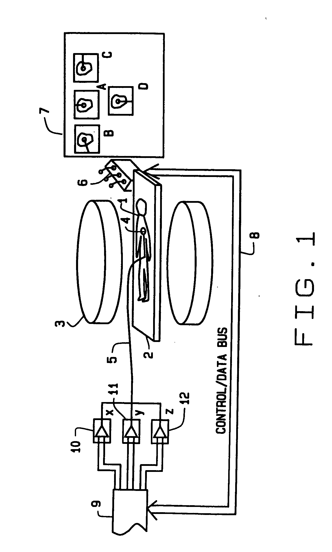
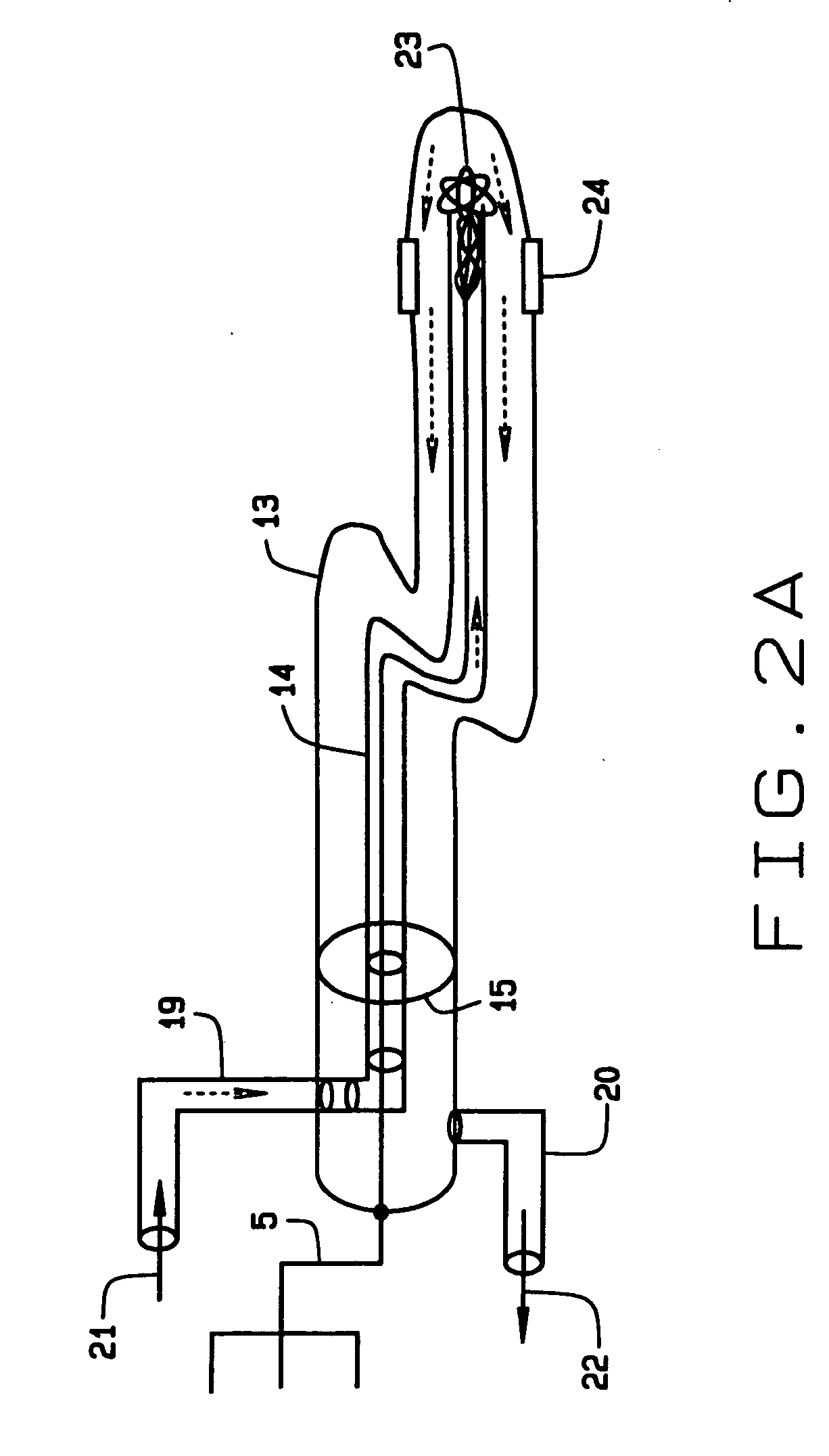
[0035] Referring to the drawings, FIG. 1 is a schematic of a system for carrying out a stereotactic procedure in accordance with the method of this invention. A patient 1 rests on the gurney or transport table 2 of an interventional MR imager 3, as supplied, for example, by Fonar Corp., Melville, N.Y. The procedure might alternatively be carried out inside the bore of a standard high field MR scanner, as supplied, for example, by Philips Medical Systems, Best, The Netherlands. A catheter 4 is disposed within the body of the patient 1. Leads 5 from the catheter 4 are connected to the power supplies or amplifiers 10, 11, 12 each of which drives one of three coils located inside the tip of the catheter 4. The power supplies 10, 11, 12 are controlled by an algorithm resident in the host computer 9. The physician (not shown) views the location of the catheter tip inside the body and the structure of the body part on the monitors 7 of the MR scanner 3. The monitors 7 show the sagittal, ax...


PUM


Abstract

A method of magnetically manipulating a medical device within a body part of a human patient in conjunction with MR imaging includes applying a navigating magnetic field with magnets from the MR imaging device, and changing the magnetic moment of the medical device to change the orientation of the medical device within the body part

Description

FIELD OF THE INVENTION [0001] This invention relates to an apparatus for navigating medical devices within the body to sites of treatment delivery, and methods of using this apparatus to achieve this navigation. More specifically, this invention relates to the use of a magnetic field from an MR imaging device to navigate a magnetic medical device within the body. BACKGROUND OF THE INVENTION [0002] The need for improved surgical navigation techniques stimulated the development of magnetic stereotaxis as a novel means for guiding a surgical implant, such as a catheter, along nonlinear paths within a body part. In particular, it is useful in intraparenchymal applications within the brain, where linear stereotactic techniques (either framed or frameless) do not permit the probe to follow single-pass curvilinear paths to a target location deep within the brain, as first taught by Howard et al. in U.S. Pat. No. 4,869,247 incorporated herein by reference. Howard et al. subsequently taught ...

Claims


Application Information

Patent Timeline
IPC IPC(8): A61B5/055A61B5/06A61B19/00A61M25/01A61M25/095G01R33/28
CPCA61B5/055A61B5/06G01R33/285A61B2019/2261A61M25/01A61B2019/2253A61B34/73A61B2034/732
Inventor GILLIES, GEORGE T.HASTINGS, ROGER N.GARIBALDI, JEFFREY M.BROADDUS, WILLIAM C.
Owner UNIV OF VIRGINIA ALUMNI PATENTS FOUND
Learn More