Signal transmitter

Inactive Publication Date: 2005-06-02
PANASONIC CORP
View PDF15 Cites 43 Cited by
  • Summary
  • Abstract
  • Description
  • Claims
  • Application Information

AI Technical Summary

Benefits of technology

[0017] The object of the invention is to provide a signal transmitter that can compensate for thermal characteristics of a radio frequency power amplifier efficiently and correctly.
[0019] According to this configuration, since the output power of the radio frequency power amplifier is detected, it is possible to correctly detect the channel temperature of the radio frequency power amplifier. Accordingly, a correction is carried out correctly. Additionally, a simple configuration does not allow an increase in power consumption. Hence, a correct compensation of the temperature characteristics of the amplifier can be carried out while maintaining high efficiency of the signal transmitter.
[0021] Also in the other prior art, the output signal of the high output power amplifier is subjected to a frequency conversion and then a quadrature detection, and the compensation value table is updated by resultant I and Q data (IQ data). As opposed to this, according to the signal transmitter of the first invention, the output voltage is detected, so that a configuration is simple and an increase in power consumption will be suppressed. Hence, a correct compensation of the temperature characteristics of the amplifier can be carried out while maintaining high efficiency of the signal transmitter.
[0024] According to this configuration, since the output power of the radio frequency power amplifier is detected, it is possible to correctly detect the channel temperature of the radio frequency power amplifier, and since a configuration is simple, an increase in power consumption will be suppressed, thereby making it possible to correctly compensate the temperature characteristics while maintaining highly efficiency of the signal transmitter using the EER method.
[0026] In the other prior art, the output signal of the high output power amplifier is subjected to a frequency conversion and then a quadrature detection, and the compensation value table is updated by using the I and Q data (IQ data) obtained by quadrature detection. As opposed to this, according to the signal transmitter of the second invention, since a configuration for detecting the output power amplitude is simple, an increase in power consumption will be suppressed. Hence, a correct compensation of the temperature characteristics of the amplifier can be carried out while maintaining high efficiency of the signal transmitter. Additionally, a temperature correction can be performed without spectral degradation in the EER method having few spectrum mask margin.
[0028] Generally, since the operating bandwidth of the phase-amplitude separation means (including DAC) is hundreds of MHz at most, when the carrier frequency exceeds a GHz order, it cannot manage this frequency order. However, according to this configuration, by using a quadrature modulator or the like which is, for example frequency converting means, it becomes easily possible to upconvert the carrier frequency into the GHz band or the like.

Problems solved by technology

Additionally, a simple configuration does not allow an increase in power consumption.

Method used


Image

  • Signal transmitter
  • Signal transmitter
  • Signal transmitter

Examples


first embodiment

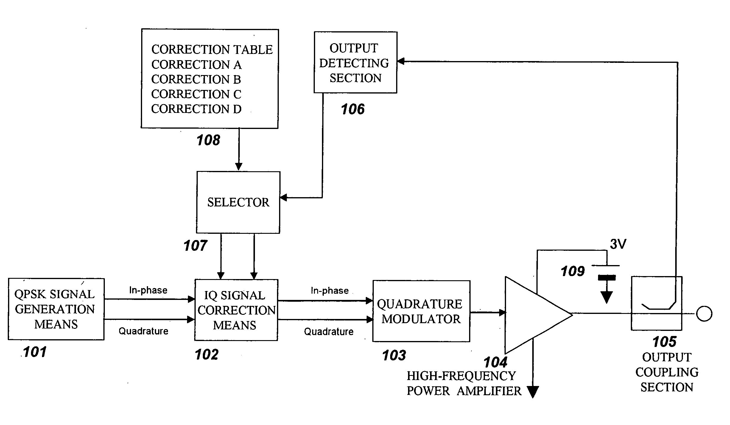
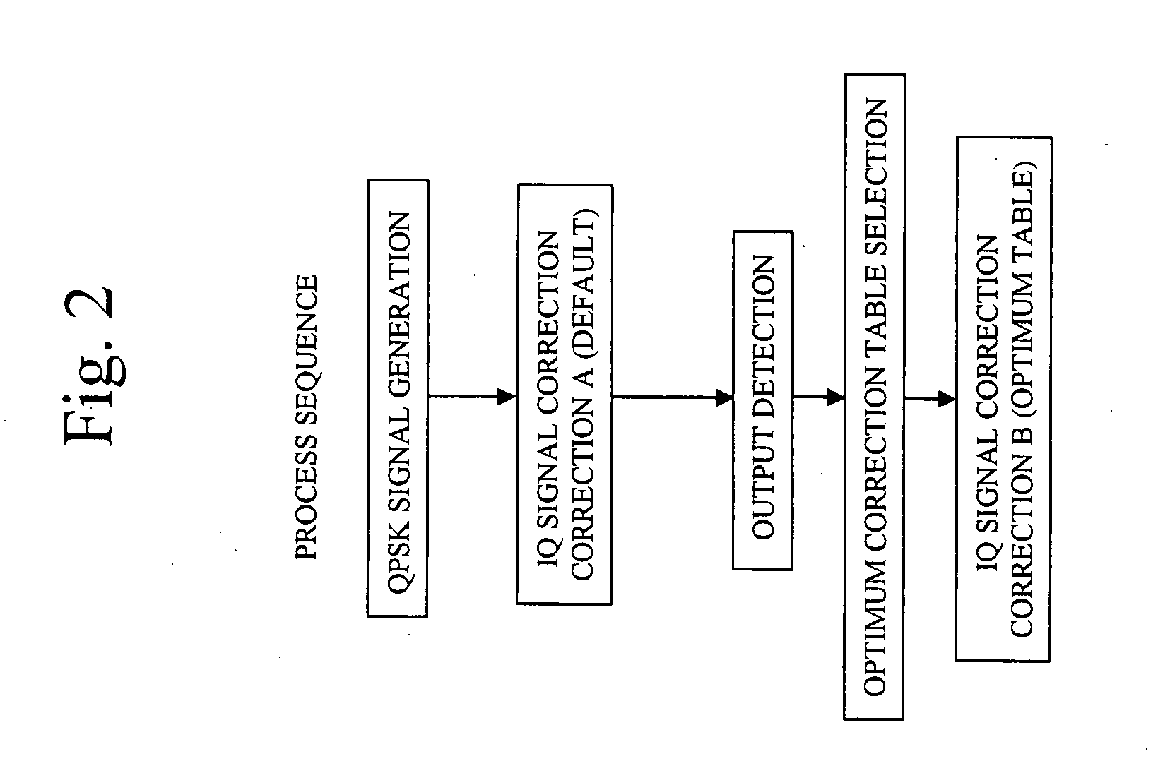
[0037] Hereafter, referring to the drawings, description will be made of embodiments according to the present invention. In this embodiment, QPSK (Quadrature Phase Shift Keying) is considered as a modulated wave. The QPSK method is a four-ary digital modulation scheme that maps an input digital signal onto X-Y coordinates by a vector synthesis of an In-Phase signal component (I) that has the same vector direction as an X-axis and a Quadrature signal component (Q) that is shifted by 90 degrees from the In-Phase signal component and has the same vector direction as a Y-axis.

[0038]FIG. 1 is shows a block diagram of a signal transmitter of a first embodiment of the present invention. As shown in FIG. 1, this signal transmitter comprises QPSK signal generating means 101, IQ signal correction means 102, a quadrature modulator 103, a radio frequency power amplifier 104, an output coupling section 105, an output detecting section 106, a selector 107, a correction table 108, and a power sup...

second embodiment

[0054] Hereafter, referring to the drawings, description will be made of a second embodiment according to the present invention. In this embodiment, an OFDM modulated wave signal is considered as the modulated wave signal. As a system using OFDM, it includes a wireless LAN system of IEEE802.11a specification, for example. In a wireless LAN system, respective 52 subcarriers which perpendicularly intersect to each other are modulated using, for example 64 QAM technology, and respective modulated subcarriers are transformed by using a inverse Fourier transform scheme and are then multiplexed to generate an OFDM modulated signal. The 52 subcarriers are separated to each other by 312.5 kHz, respectively, and occupy a bandwidth of 52×312.5=16.25 MHz.

[0055]FIG. 3 shows a block diagram of a signal transmitter for achieving an EER method according to the embodiment of the present invention. As shown in FIG. 3, this signal transmitter comprises OFDM signal generating means 301, phase-amplitu...


PUM


Abstract

An amplitude component and a phase component among modulating signals are supplied into a radio frequency wave input terminal and a power supply terminal of a radio frequency power amplifier, respectively, and an original modulated wave is obtained from an output of the radio frequency power amplifier. The output of the radio frequency power amplifier is detected by an output detecting section, correction data to a detection voltage closest to the detection voltage among correction datatables which have been measured in various temperature environments and stored in advance are selected by a selector, and correction of an amplitude component and a phase component is performed by phase-amplitude correction means. Thereby enabling EER operation without spectrum degradation.

Description

BACKGROUND OF THE INVENTION [0001] 1. Field of the Invention [0002] The present invention is related to a wireless transmitter. [0003] 2. Description of the Prior Art [0004] Linear operation is generally required for a radio frequency power amplifier used for transmitting signal power to an antenna when a signal modulation method that accompanies amplitude modulation is used, especially when a M-ary modulation method such as a QAM(Quadrature Amplitude Modulation) method is used. For this reason, class A or class AB operation has been conventionally used for a radio frequency power amplifier. [0005] However, on the other hand, communication technologies that use multiple carriers such as an OFDM (Orthogonal Frequency Division Multiplex) technology have become commonly used in accordance with the development of broadband communications. Consequently, in such a case, high operational efficiency cannot be expected any more for a conventional radio frequency power amplifier that is opera...

Claims


Application Information

Patent Timeline
IPC IPC(8): H01Q11/12H03F1/30H03F1/32H03F3/24H04B1/04H04L27/20H04L27/36
CPCH03F1/3247H04B2001/0433H03F1/3294H03F1/34H03F3/24
Inventor TANABE, MITSURUTANAKA, KOICHIRO
Owner PANASONIC CORP
Why Eureka
Try Eureka