
Control device for motor-driven 4WD vehicle and related control method

a technology of control device and 4wd vehicle, which is applied in the direction of motor/generator/converter stopper, electric motor propulsion transmission, electric generator control, etc., can solve the problems of increasing the number of component par, increasing and affecting the operation of the vehicle, so as to increase the weight of the vehicle and increase the cost

Inactive Publication Date: 2005-06-02
NISSAN MOTOR CO LTD
View PDF10 Cites 6 Cited by
  • Summary
  • Abstract
  • Description
  • Claims
  • Application Information

AI Technical Summary

Benefits of technology

[0006] The present invention has been made to address the above issues encountered in the related art and has an object to provide a control device and control method, for a motor-driven 4WD vehicle, which are able to simplify a device structure.

Problems solved by technology

However, with such related art vehicles, since an electric power generator for driving wheels, and an electric power generator for supplying electric power to an electrical equipment of a vehicle are separately equipped, the number of component par increases, causing an issue of restriction in layout.
Also, the increase in the number of component part results in an increase in weight of the vehicle, causing an issue of an increase in costs.

Method used


Image

  • Control device for motor-driven 4WD vehicle and related control method
  • Control device for motor-driven 4WD vehicle and related control method
  • Control device for motor-driven 4WD vehicle and related control method

Examples


first embodiment

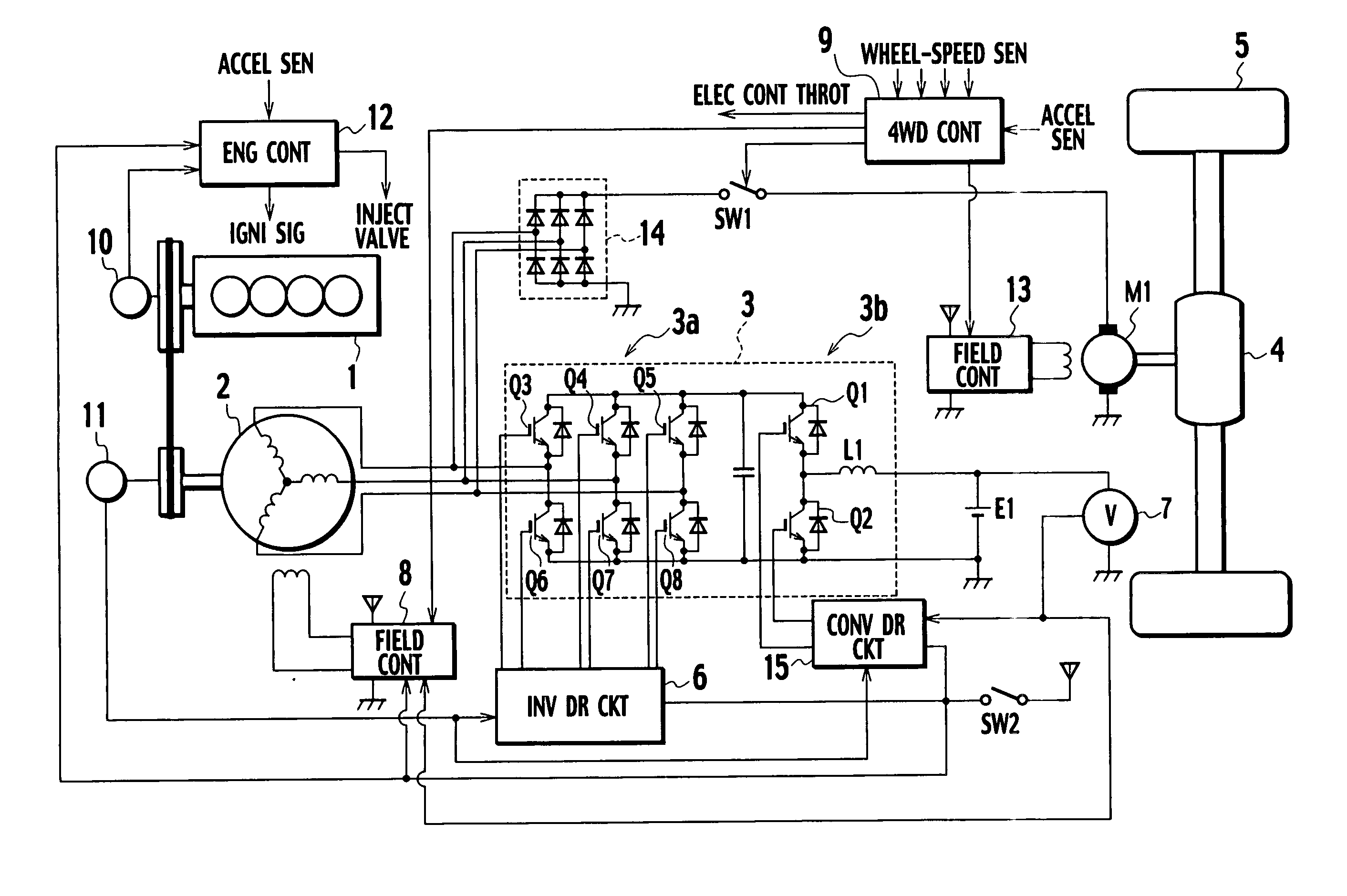
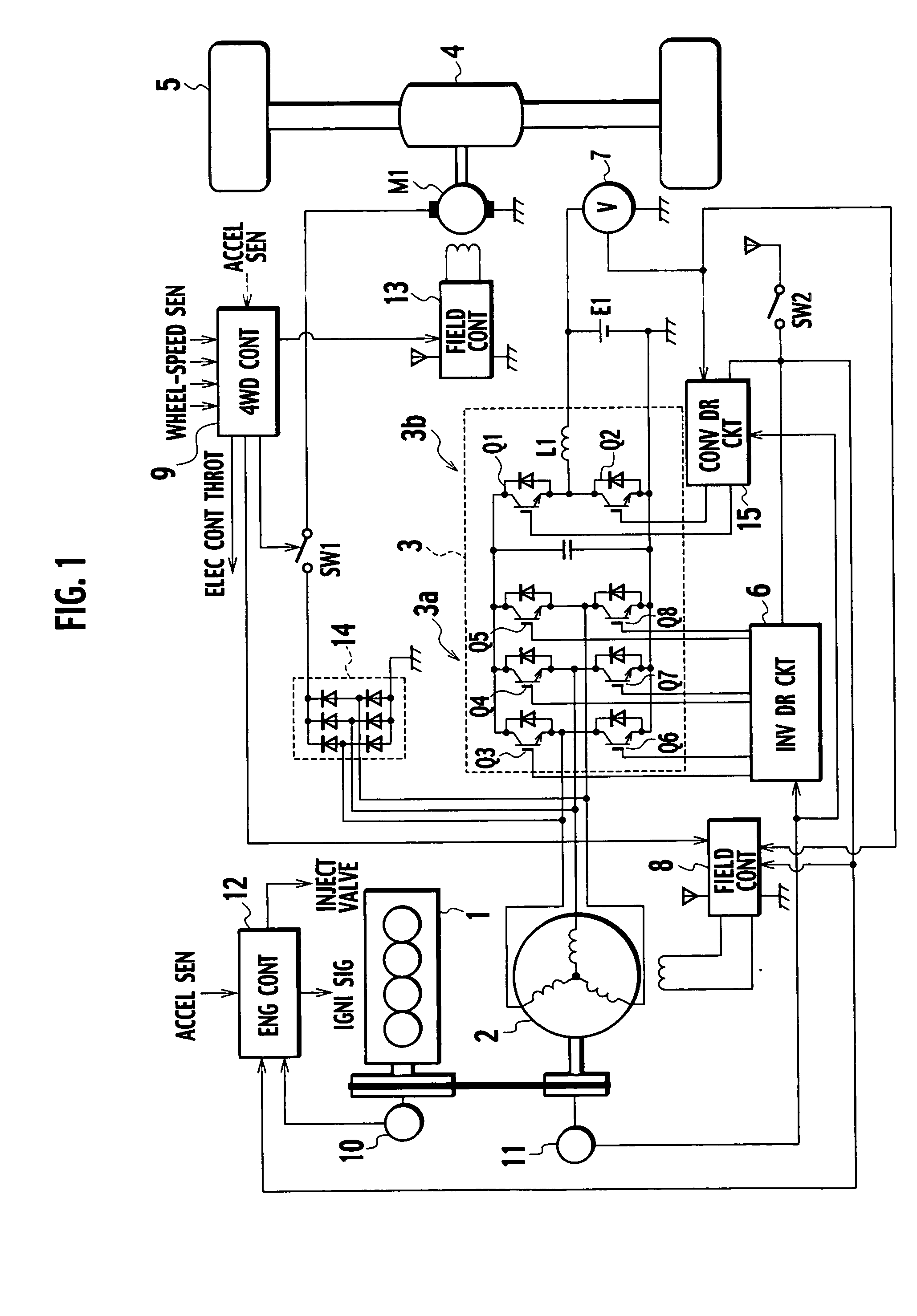
[0017] A control device of a first embodiments serves to control a vehicle with a structure wherein either of the front wheels or rear wheels are driven with an ge and the others are driven with a motor. As shown in FIG. 1, the vehicle is comprised of an engine 1, a 42V alternator (motor-generator) (ALT) 2 connected to the engine I through a belt to transmit rotational power of the engine 1 to generate AC power (e.g., three-phase AC power) at 42V (a first rated voltage) and operative to serve as an electric motor during engine start-up, a diode bridge circuit 14 (rectifying means) that rectifies AC power generated by the 42V alternator 2, a set-up and set-down inverter 3, and a 14V battery (electrical equipment) (BAT) E1 that supplies driving electric power to a variety of instrumented equipments installed on a vehicle.

[0018] Furthermore, the vehicle is comprised of a DC motor (MOT) M1 that is supplied with DC power, rectified by the diode bridge circuit 14, to be rotationally driv...

second embodiment

[0054] Next, description is made of a second embodiment according to the present invention. As shown in FIG. 6, a control device of the second embodiment is comprised of the engine 1, the 42V alternator (ALT) 2, a set-up and set-down inverter 3A, the diode bridge circuit 14, the motor M1 driven with DC power, a driver circuit (DR CKT) 16, the 14V battery E1 and the voltage sensor 7.

[0055] Further, the control device is comprised of the engine speed sensor 10 that detects rotational speed of the engine 1, the position sensor 11 for detecting the rotator position of the 42V alternator 2, the engine controller (ENG CONT) 12 for controlling the engine 1, the 4WD controller (4WD CONT) 9 that controls 4WD drive, the field control section 8 for controlling field current flowing across the field winding of the motor M1, and the field control section (FIELD CONT) 13 that controls field current flowing across the field winding of the motor M1.

[0056] A negative terminal of the 14V battery E1...


PUM


Abstract

A control device for a motor-driven vehicle comprises a 42 v alternator (motor-generator) driven by an engine to generate three-phase AC power with 42 volts, a set-up and set-down inverter rectifying and setting down three-phase AC power, generated by the 42 v alternator, to DC power with 14 volts, and a 14V battery supplied with and charged with DC power with 14 volts outputted from the set-up and set-down inverter. A diode bridge circuit rectifies AC power with 42 volts, generated by the 42V alternator, to DC power by which a motor is rotationally driven to render the vehicle operative in 4WD drive mode.

Description

BACKGROUND OF THE INVENTION [0001] 1. Field of the Invention [0002] The present invention relates to a control device and related control method for a motor-driven 4WD vehicle wherein either of front wheels and rear wheels are available to be driven by an engine and the others are available to be driven by a motor. [0003] 2. Description of the Related Art [0004] In the related art 4WD vehicles have heretofore been known wherein front wheels are driven with a drive power, generated buy an engine, by which an electric power generator is driven to generate electric power which in turn rotationally drives a motor to provide a drive power by which rear wheels are driven (see Japanese Patent Laid Open Publication Nos. 2002-152911 and 2002-200932). SUMMARY OF THE INVENTION [0005] However, with such related art vehicles, since an electric power generator for driving wheels, and an electric power generator for supplying electric power to an electrical equipment of a vehicle are separately eq...

Claims


Application Information

Patent Timeline
IPC IPC(8): B60W20/00B60K6/44B60K6/52B60K17/356B60L15/20B60L50/10B60L50/12B60L50/16B60W10/06B60W10/08B60W10/26
CPCB60K6/28B60K6/52B60L11/06B60L11/14B60W10/06Y02T10/70B60W20/00Y02T10/7077Y02T10/7258Y02T10/6265B60W10/26B60L50/12B60L50/16Y02T10/62Y02T10/7072Y02T10/72B60K17/356B60W20/10
Inventor ISHIKAWA, YASUKITAKANAMI, WATARU
Owner NISSAN MOTOR CO LTD
Learn More