
Reel clutch device and method for tape recorders

Inactive Publication Date: 2005-06-02
SAMSUNG ELECTRONICS CO LTD
View PDF12 Cites 3 Cited by
  • Summary
  • Abstract
  • Description
  • Claims
  • Application Information

AI Technical Summary

Benefits of technology

[0015] The present invention has been developed in order to solve the above drawbacks associated with the conventional arrangement. An aspect of the present invention is to provide a reel clutch device and method for tape recorders which can be manufactured at low cost and transmit a constant torque regardless of variations of ambient environment.
[0020] As described above, the reel clutch device and method for tape recorders according to the present invention can be manufactured at low manufacturing cost due to low supplies cost and less assembly work.
[0021] Furthermore, the reel clutch device and method according to the present invention can transmit a constant torque regardless of variations of ambient environment.

Problems solved by technology

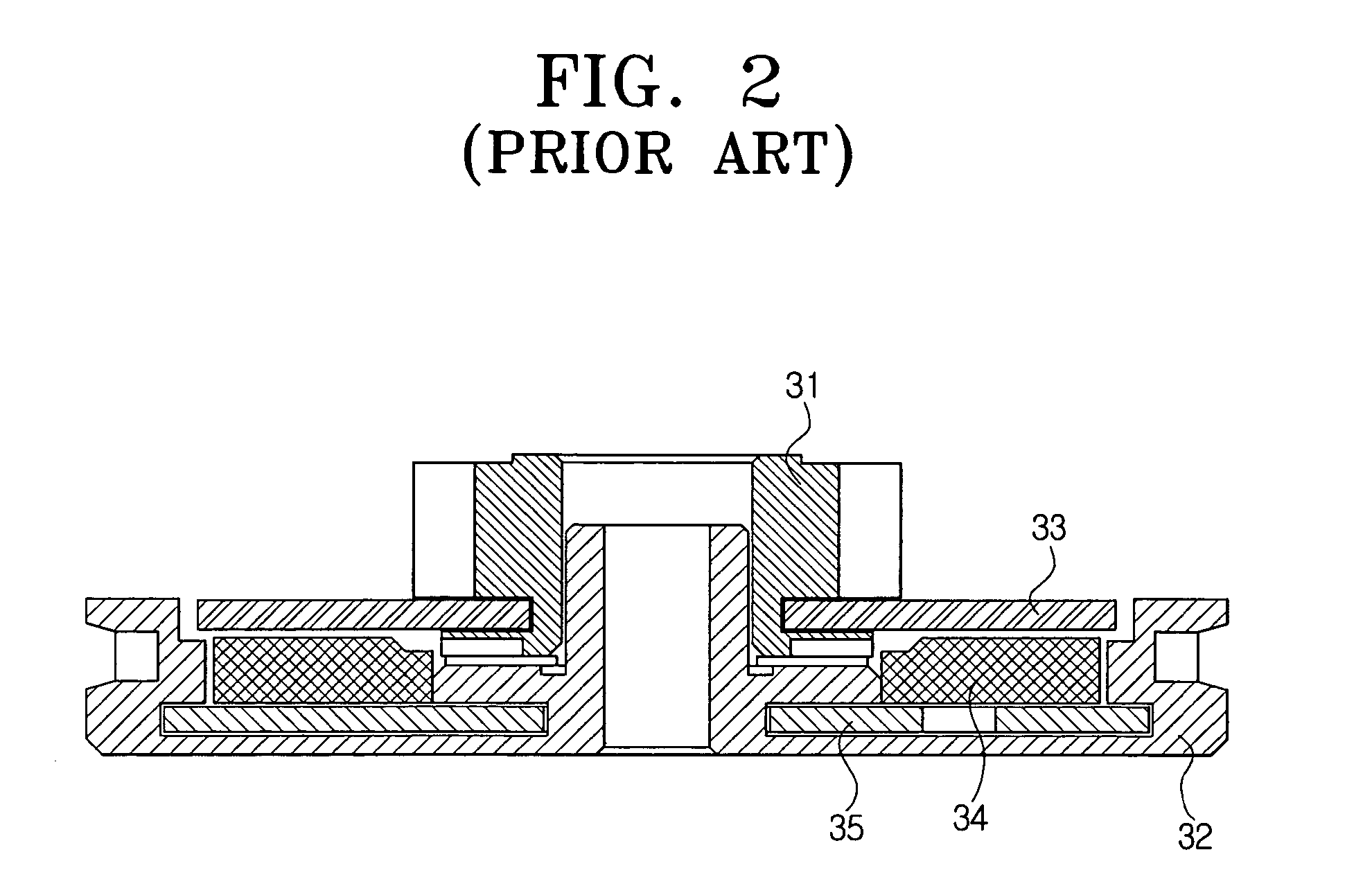
However, in the described reel clutch device, the iron-plate base 35 supporting the magnet 34 is press-fitted to the reel gear 32 in an inserting manner, and the iron plate 33 is press-fitted to the reel disk 31 in an outserting manner, which results in problems with assembling the device.
Further, the magnet is expensive.
However, the reel clutch device using the felt has less functional reliability due to variations of transmission torque resulting from the characteristics of the felt which are affected by temperature and humidity.
In particular, the felt reel clutch device has a problem in transmitting a constant torque since the torque rapidly increases in high humidity and goes through severe variations in its magnitude at low temperatures.

Method used


Image

  • Reel clutch device and method for tape recorders
  • Reel clutch device and method for tape recorders
  • Reel clutch device and method for tape recorders

Examples


Embodiment Construction

[0030] Embodiments of the present invention will be described in greater detail with reference to the accompanying drawings.

[0031] In the following description, the same drawing reference numerals are used for the same elements in different drawings. Examples are used to describe embodiments of the present invention. Thus, it should be apparent that the present invention can be performed without the examples shown without departing from the scope of the invention. Also, well-known functions or constructions are not described in detail for conciseness.

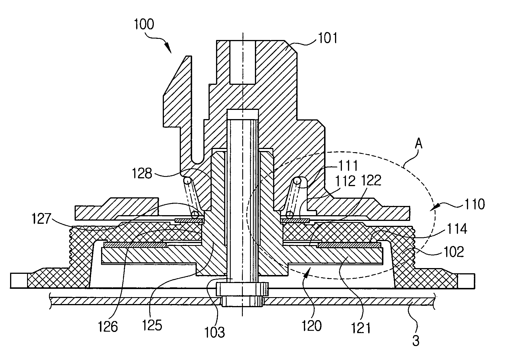
[0032]FIG. 4 is a cross-sectioned view showing a reel disk assembly including a reel clutch device for tape recorders according to an embodiment of the present embodiment, FIG. 5 is an enlarged cross-sectioned view showing a portion A of FIG. 4, and FIG. 6 is an exploded perspective view showing the reel clutch device for tape recorders shown in FIG. 4.

[0033] Referring to FIG. 4 to FIG. 6, a reel clutch device 110 for tape recorders ...


PUM


Abstract

A reel clutch device and method for tape recorders is disclosed. The reel clutch device has an elastic member mounted in the lower side of the reel disk; a reel washer mounted between the elastic member and the reel gear to be in frictional contact with the top surface of the reel gear; The reel clutch device and method further comprises a reel plate mounted to be in frictional contact with the bottom surface of the reel gear; and a reel stopper mounted on the lower side of the reel plate, and for adjusting a gap between the reel disk and the reel gear in order for adequate friction torque to occur between the reel washer and the top surface of the reel gear and the reel plate and the bottom surface of the reel gear.

Description

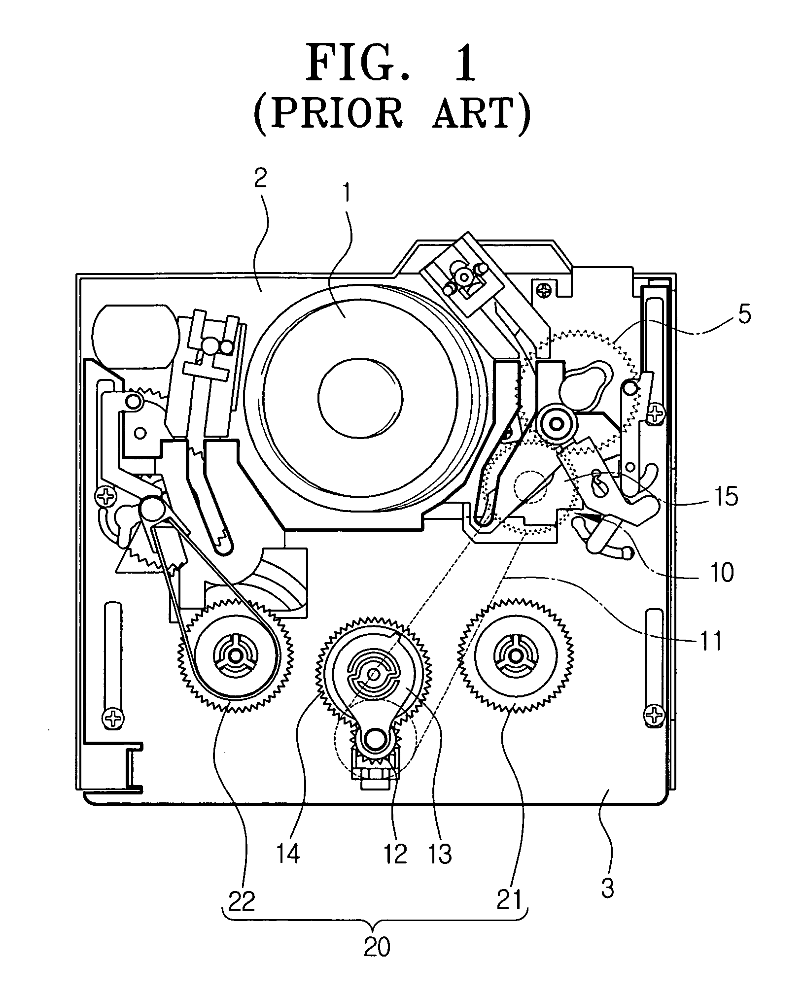
[0001] This application claims benefit under 35 U.S.C.§ 119(a) from Korean Patent Application No. 2003-86264, filed on Dec. 1, 2003, the entire contents of which is incorporated herein by reference. BACKGROUND OF THE INVENTION [0002] 1. Field of the Invention [0003] The present invention relates to a reel disk assembly for tape recorders that plays a tape cassette. More particularly, the present invention relates to a reel clutch device and method for tape recorders which transfers the rotary torque of a reel gear to a reel disk. [0004] 2. Description of the Related Art [0005] Tape recorders are devices for recording information on a recording medium such as magnetic tapes and reproducing the recorded information. Examples of tape recorders are video cassette tape recorders(VCRs), camcorders, and so on. [0006] Referring to FIG. 1, a tape recorder has a main deck 2 on which a head drum 1 is rotatably mounted, a sub-deck 3 mounted on the main deck 2 and able to be loaded and unloaded ...

Claims


Application Information

Patent Timeline
IPC IPC(8): G11B15/30G11B15/32G11B15/50
CPCG11B15/50G11B15/32
Inventor SEO, JAE-KABOH, JEONG-HYEOBKIM, JUN-YOUNG
Owner SAMSUNG ELECTRONICS CO LTD
Learn More