
Method and apparatus to pre-form two or more integrated connectorless cables in the flexible sections of rigid-flex printed circuit boards

a technology of printed circuit board and flexible section, which is applied in the direction of fixed connection, metal working apparatus, manufacturing tools, etc., can solve the problems of shortening the service life of the rigid-flex printed circuit board structure, reducing the fatigue life of the conductor, and immediate electrical failure, so as to reduce the potential strain and stress in the conductor layer

Inactive Publication Date: 2005-05-26
IBM CORP
View PDF19 Cites 6 Cited by
  • Summary
  • Abstract
  • Description
  • Claims
  • Application Information

AI Technical Summary

Benefits of technology

[0021] Although all of the foregoing prior art publications relate to various aspects of explicabilities of flexible cables or electrical wiring, none of these concern themselves, unlike the present invention, with enabling integrated connectorless flexible cables constituting electrically conductive connections within flexible printed circuit board sections to be preformed by an apparatus causing integrated connectorless flexible cable sections located in a region approximately at the center of the length of the flexible printed circuit board section intermediate to rigid printed circuit board sections, whereby this preforming outwardly bows each integrated connectorless flexible cable so as ensure a specified permanently separation of the integrated connectorless flexible cables; so as to thereby reduce and more evenly distribute stress and strains in the conductor in the integrated connectorless flexible cables during folding and unfolding of the flexible printed circuit board sections. This preforming also prevents creasing of the integrated connectorless flexible cables during folding and unfolding inasmuch as such creasing would significantly reduce the fatigue life of the conductors of possibly cause immediate electrical failure.
[0022] In order to attain the advantages, pursuant to the invention, an apparatus which comprises a tool constituted of an elongated cylindrical member has a tapered leading end which narrows into an ultra-thin flat end section of a blade-like configuration, and which is adapted to be pushed between the integrated connectorless flexible cables and so as to preform these integrated connectorless flexible cables and cause them to yield in a predetermined outwardly bowed permanent relationship between the rigid printed circuit board sections at the opposite ends thereof. This outward bowing of the integrated connectorless flexible cable sections imparts a permanent deformation thereto responsive to the insertion of the tool therebetween and advancing the tool between the integrated connectorless flexible cable sections to permanently form a widened spacing therebetween. Thereafter, upon the folding or bending of the printed circuit boards relative to each other from a two-dimensional into a three-dimensional configuration which imparts a bend to the flexible printed circuit board sections, an outer integrated connectorless flexible cable section will be flexed so as to assume what may generally be described as a simple arc whereas an inner integrated connectorless flexible cable section responsive to the bend of the flexible printed circuit board section will assume the configuration of an inwardly depending loop, in the general form of an “omega” which, at times is referred to as a so-called omega loop. This bending into an omega loop of the inner integrated connectorless flexible cable section will prevent any undue excessive stresses or strains to be encountered by the conductor layer or layers in the integrated connectorless flexible cables which would result in a shortening of the service life of the rigid-flex printed circuit board structure caused by the folding and unfolding thereof.
[0024] Another object of the present invention resides in providing an apparatus comprising a tool which is adapted to be inserted between integrated connectorless flexible cable sections therein so as to separate and permanently deform the integrated connectorless flexible cable sections relative to each other, whereby folding of the printed circuit boards into a three-dimensional configuration causes an outer integrated connectorless flexible cable section to assume a generally simple arc, whereas an inner integrated connectorless flexible cable section assumes an inwardly depending loop-shaped configuration.
[0026] Yet another object of the present invention resides in the provision of a method for deforming integrated connectorless flexible cable sections extending intermediate rigid printed circuit boards so as to reduce potential strains and stresses in conductor layers of the integrated connectorless flexible cable sections responsive to three dimensional deformation or folding of the rigid printed circuit board sections relative to each other.
[0027] Still another object of the present invention resides in the provision of a method wherein responsive to a permanent deformation of integrated connectorless flexible cable sections within a flexible printed circuit board section which extends between rigid printed circuit board sections, upon the bending thereof through an angular displacement, an outer integrated connectorless flexible cable section will assume a generally simple bent arc whereas an inner integrated connectorless flexible cable section of the flexible printed circuit board section will assume an inwardly depending loop configuration, so as to thereby reduce any strains encountered in the conductive layer or layers of the integrated connectorless flexible cable sections responsive to the bending of the flexible printed circuit board sections.

Problems solved by technology

This preforming also prevents creasing of the integrated connectorless flexible cables during folding and unfolding inasmuch as such creasing would significantly reduce the fatigue life of the conductors of possibly cause immediate electrical failure.
This bending into an omega loop of the inner integrated connectorless flexible cable section will prevent any undue excessive stresses or strains to be encountered by the conductor layer or layers in the integrated connectorless flexible cables which would result in a shortening of the service life of the rigid-flex printed circuit board structure caused by the folding and unfolding thereof.

Method used


Image

  • Method and apparatus to pre-form two or more integrated connectorless cables in the flexible sections of rigid-flex printed circuit boards
  • Method and apparatus to pre-form two or more integrated connectorless cables in the flexible sections of rigid-flex printed circuit boards
  • Method and apparatus to pre-form two or more integrated connectorless cables in the flexible sections of rigid-flex printed circuit boards

Examples


Embodiment Construction

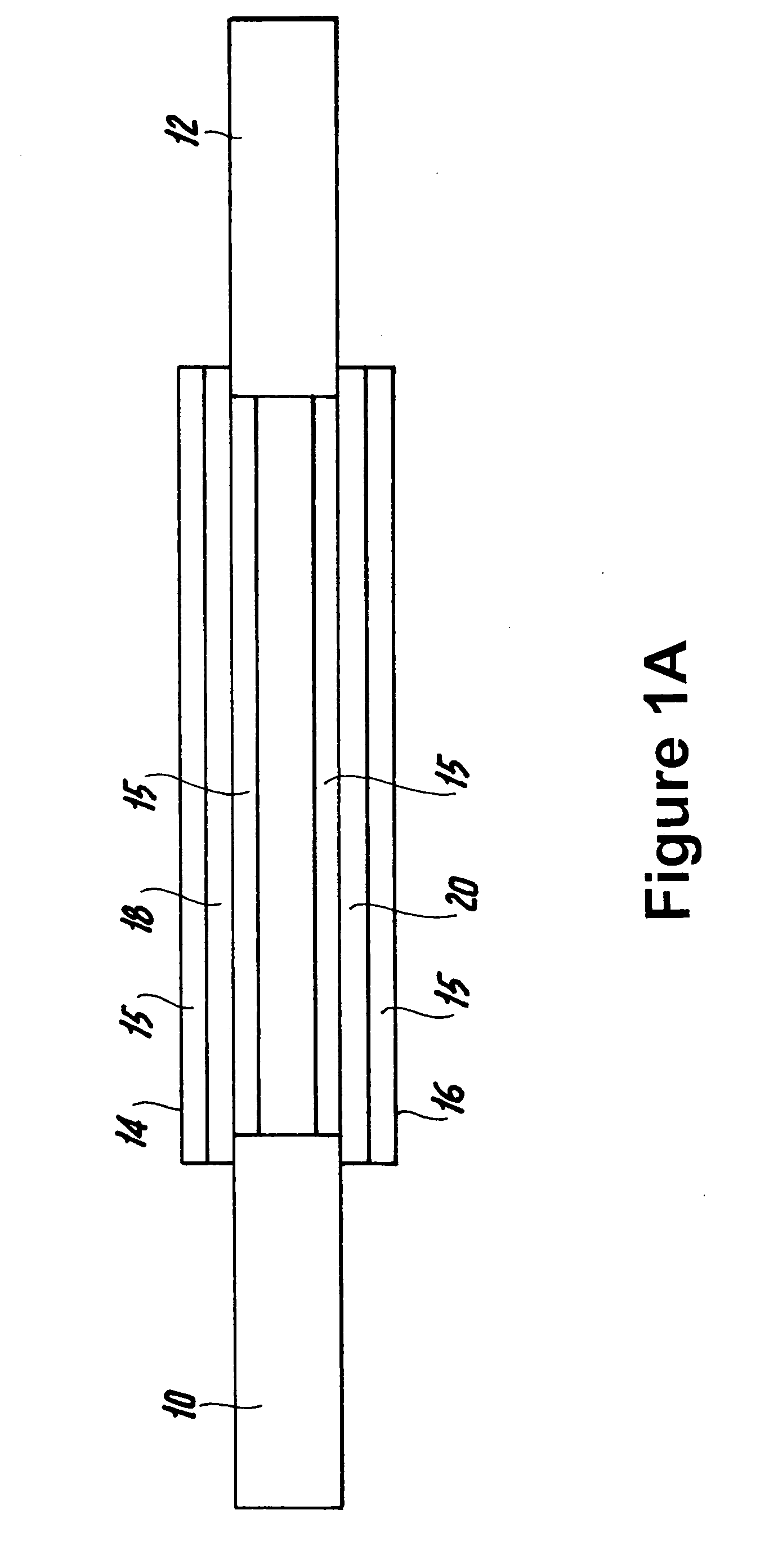
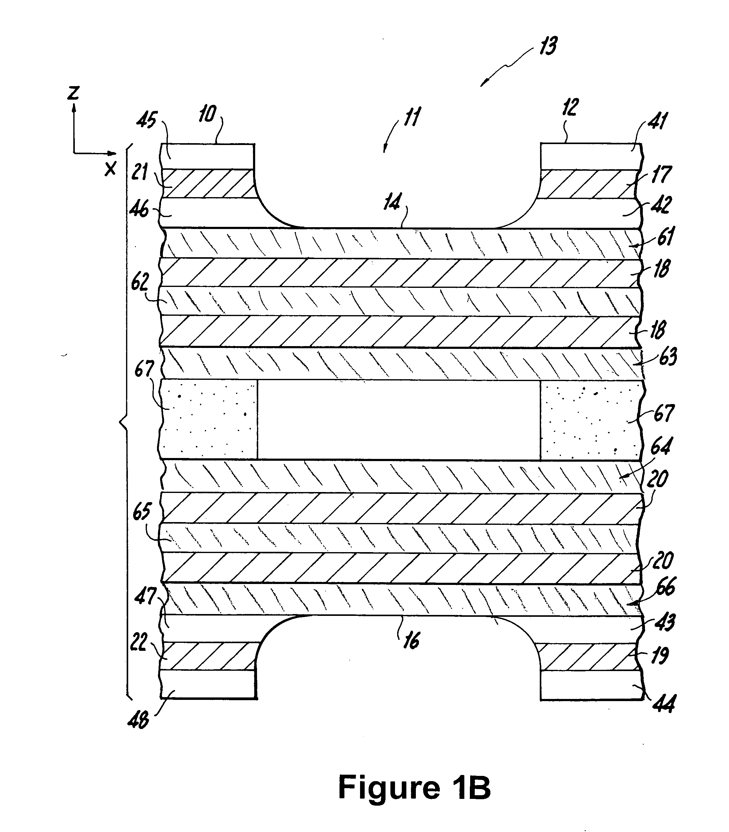
[0035] Referring now specifically to FIGS. 1A and 1B of the drawings, there is illustrated a rigid-flex printed circuit board 13 comprised of a first rigid printed circuit board section 10, and with a second rigid printed circuit board section 12 interconnected therewith through a flexible printed circuit board 11.

[0036] In FIG. 1A, rigid printed circuit board section 10 has electrical components 80, 81, and 82 surface mounted to it. Rigid printed circuit board section 12 has electrical components 83 and 84 surface mounted to it. Electrical components 80, 81, 82, 83 and 84 are typically semiconductor chips such as microprocessors read-only memory (ROM) chips containing microcode used by microprocessors chips, or random-access memory (RAM) chips for buffering input to or output from the microprocessor chips. Because of the delicate nature of electrical components 80, 81, 82, 83, and 84, they are mounted to rigid printed circuit board sections 10 and 12.

[0037]FIG. 1B illustrates tha...


PUM

PropertyMeasurementUnit
Fractionaaaaaaaaaa
Fractionaaaaaaaaaa
Lengthaaaaaaaaaa

Abstract

A method for preforming of two or more flexible cables in an arrangement consisting of a combination of rigid printed circuit boards and flexible cable sections extending therebetween. Moreover, also provided is an apparatus for the preforming of two or more flexible cable sections of a combination of rigid printed circuit boards and therewith interposed flexible cable sections which are adapted to interconnect the rigid printed circuit boards. The apparatus consists of a tool constituted of an elongated cylindrical member having a tapered leading end which narrows into an ultra-thin flat end section of a blade-like configuration, and which is adapted to be pushed between the flexible cables and so as to preform the flexible cable sections and cause them to yield in a predetermined outwardly bowed permanently relationship between the rigid printed circuit boards at the opposite ends thereof to lengthen the fatigue life of the conductors in the flexible cable sections.

Description

BACKGROUND OF THE INVENTION [0001] 1. Field of the Invention [0002] The present invention relates to a method for preforming of two or more integrated connectorless flexible cables in flexible sections of a rigid-flex printed circuit board consisting of a combination of rigid printed circuit board sections and flexible printed circuit board sections extending therebetween. Moreover, the invention is also directed to an apparatus for the preforming of two or more integrated connectorless flexible cables in flexible sections of a rigid-flex printed circuit board consisting of a combination of rigid printed circuit board sections and therewith interposed flexible printed circuit board sections which are adapted to interconnect the rigid printed circuit board sections. [0003] In the electronic packaging industry, there are provided operatively joined wherein pluralities of rigid printed circuit board (PCB) sections which are essentially interconnected through the intermediary of flexibl...

Claims


Application Information

Patent Timeline
IPC IPC(8): H05K1/00H05K3/00
CPCH01R12/62H05K1/028H05K3/4691H05K2201/09109H05K2201/2027Y10T29/49199Y10T29/49169Y10T29/53257Y10T29/49194Y10T29/53909Y10T29/49151Y10T29/53283H01R43/00B25B27/00
Inventor RANDALL, LEE CURTISTRUMAN, THOMAS STANLEYWINARSKI, DANIEL JAMESZAMORA, GEORGE G.
Owner IBM CORP
Learn More