
Structure of thin battery covered by outer packaging film, battery pack, and method for manufacturing battery pack

a technology of outer packaging film and thin battery, which is applied in the direction of batteries, sustainable manufacturing/processing, and primary cell maintenance/service, etc., can solve the problems of ratio deterioration of battery cells, high cost, and large battery cases b>102/b>, and achieve the effect of convenient welding work

Inactive Publication Date: 2005-05-26
SONY CORP
View PDF11 Cites 60 Cited by
  • Summary
  • Abstract
  • Description
  • Claims
  • Application Information

AI Technical Summary

Benefits of technology

[0008] The present invention provides a thinner, smaller and lighter battery pack and reduces the cost by eliminating the need for a battery case constituted by two halves of a thin box.
[0009] Another aspect of the present invention is to prevent the transfer mold from pressing onto the battery cell, thereby protecting the electronic components.
[0010] A first aspect of the present invention is to eliminate the need for the conventional two halves of the battery case in such manner that a thin battery is constructed of a battery cell formed in a flat and rectangular shape, a frame portion in which the battery cell is accommodated, a circuit board unit disposed on an outer side surface of the frame portion, a cap portion mounted so as to sandwich the circuit board unit with the outer side surface of the frame portion at one ends of the frame portion and the battery cell, and an outer packaging film integrally covering the battery cell and the frame portion, wherein the side surfaces of the battery cell is enclosed by the frame portion, and the front and back surfaces of the battery cell are covered with the outer packaging film.

Problems solved by technology

Further, its cost is also high.
This makes the battery case 102 relatively large and is usually a cause of volume ratio deterioration of the battery cell 103 in the battery pack 101.

Method used


Image

  • Structure of thin battery covered by outer packaging film, battery pack, and method for manufacturing battery pack
  • Structure of thin battery covered by outer packaging film, battery pack, and method for manufacturing battery pack
  • Structure of thin battery covered by outer packaging film, battery pack, and method for manufacturing battery pack

Examples


Embodiment Construction

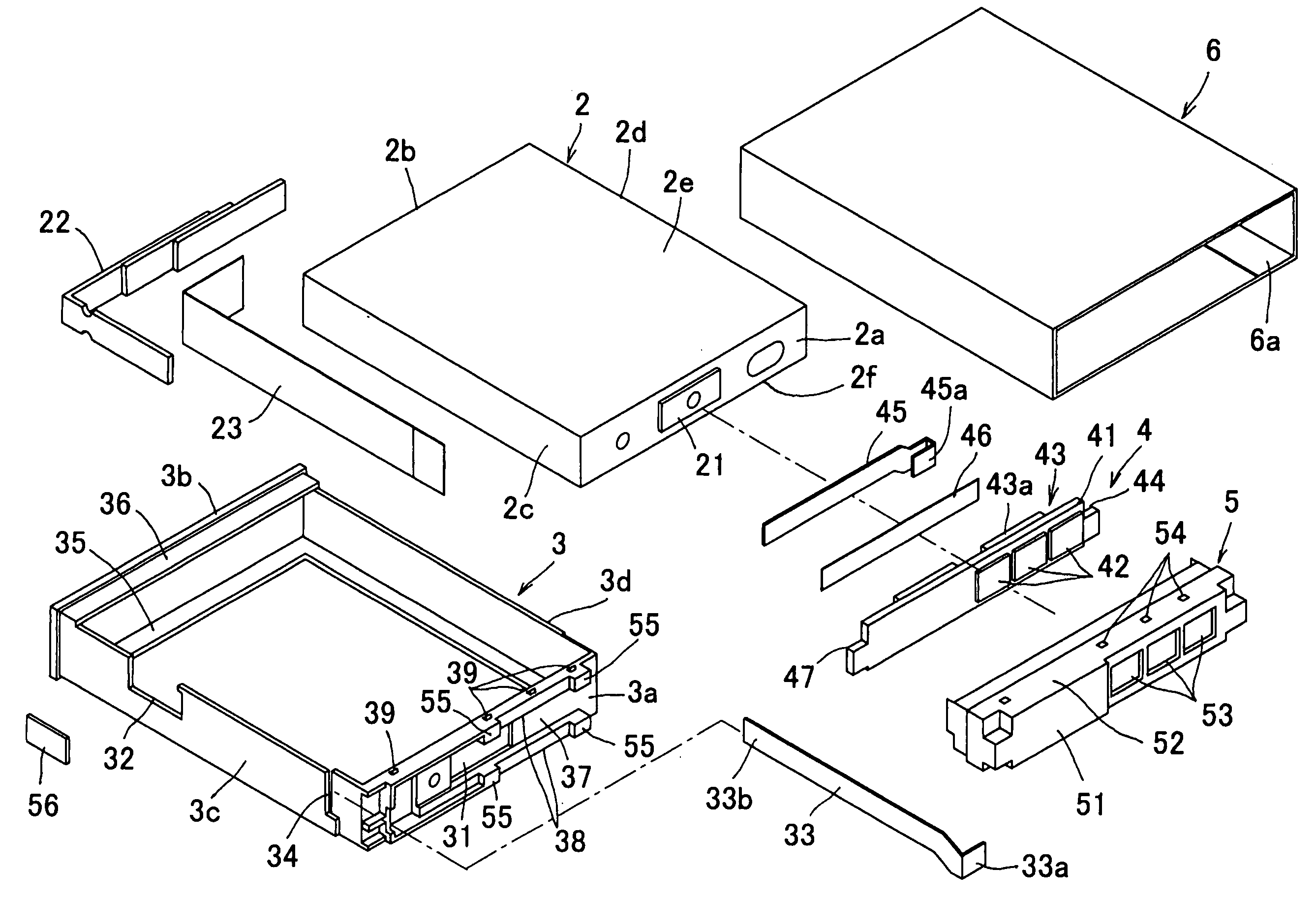
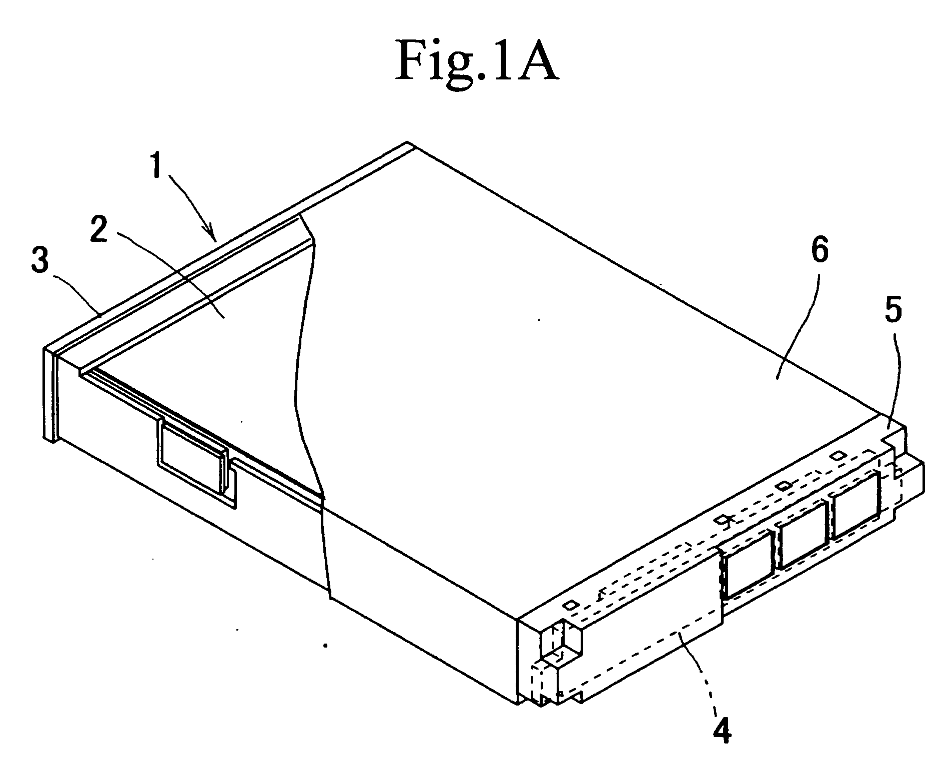
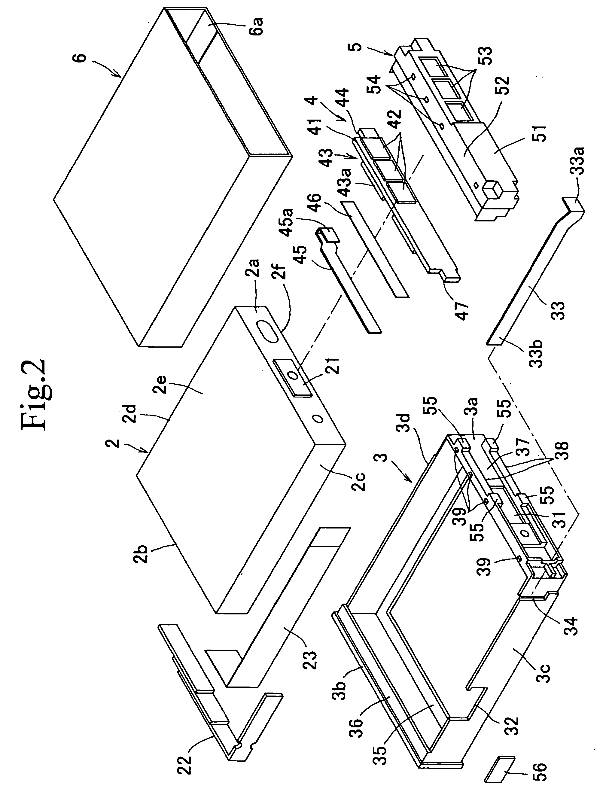
[0063]FIG. 1 is a perspective view of a battery pack 1 and FIG. 2 is an exploded perspective view of the battery pack 1. As shown in FIG. 1, the battery pack 1 has a rectangular battery cell 2, a rectangular frame portion 3 containing the battery cell 2, a circuit board unit 4 disposed on the outer side surface of the frame portion 3, a cap portion 5 mounted on one ends of the frame portion 3 and the battery cell 2 so as to sandwich the circuit board unit 4 with the outer side surface of the frame portion 3, and an outer packaging film 6 integrally covering the rectangular battery cell 2 and the frame portion 3.

[0064] The battery cell 2 is formed by covering a laminated member (battery element), which is made, for example, by sequentially laminating a positive pole, a separator and a negative pole, with a film-like outer packaging member. As shown in FIG. 2, the battery cell 2 is formed in a flat rectangular tubular form with first to fourth side surfaces 2a to 2d and a front surfa...


PUM

PropertyMeasurementUnit
Thicknessaaaaaaaaaa
Heightaaaaaaaaaa
Circumferenceaaaaaaaaaa

Abstract

To provide a thinner, lighter battery pack and to reduce the cost by eliminating the need for a battery case. A thin battery pack structure using an outer packaging film (battery pack) is constructed by a flat and rectangular shaped battery cell, a flat and rectangular shaped frame portion accommodating the battery cell, a circuit board unit disposed on the outer side surface of the frame portion, a cap portion mounted on one ends of the frame portion and the battery cell so as to sandwich the circuit board unit with the outer side surface of the frame portion, and an outer packaging film for integrally covering the rectangular battery cell and the frame portion.

Description

BACKGROUND OF THE INVENTION [0001] 1. Field of the Invention [0002] The present invention relates to a structure of a thin battery covered by an outer packaging film, a battery pack, and method for manufacturing a battery pack to be used for a battery of a mobile phone, a game machine, a notebook-type personal computer, or the like. [0003] 2. Description of Related Art [0004] As a battery structure and a battery pack, the one as shown in FIG. 10 is known. A battery pack 101 is constructed of a rectangular battery main body (referred to as a “battery cell” below) 103 containing power generation elements therein, and a circuit board unit 105 on which a plurality of electronic components 104 is mounted to constitute a protection circuit, which are accommodated in a battery case 102 constituted by two halves of a thin box. It is to be noted that, as shown in FIG. 11, the circuit board unit 105 is supported by ribs 106 formed on the battery case 102 so that the electronic components 104 ...

Claims


Application Information

Patent Timeline
IPC IPC(8): B65D85/88H01M6/50H01M10/04H01M10/44H01M50/147H01M50/55
CPCH01M2/0215H01M2/0217H01M2/0404Y10T29/49114H01M10/443H01M2200/106H01M10/0472Y02E60/10H01M50/103H01M50/147Y02P70/50H01M50/55
Inventor TAKESHITA, TOSHIOSATO, HIROAKIMIYAJIMA, YOICHISATO, HIDEYUKI
Owner SONY CORP
Learn More