
Novel device, system and method for fluorescence detection

a technology of fluorescence detection and new devices, applied in the field of new devices, systems and methods for fluorescence detection, can solve the problems of low-power, low-power, and low-power teaching of background art, and achieve the effect of low-power

Inactive Publication Date: 2005-05-26
INVERNESS MEDICAL SWITZERLAND GMBH
View PDF22 Cites 62 Cited by
  • Summary
  • Abstract
  • Description
  • Claims
  • Application Information

AI Technical Summary

Benefits of technology

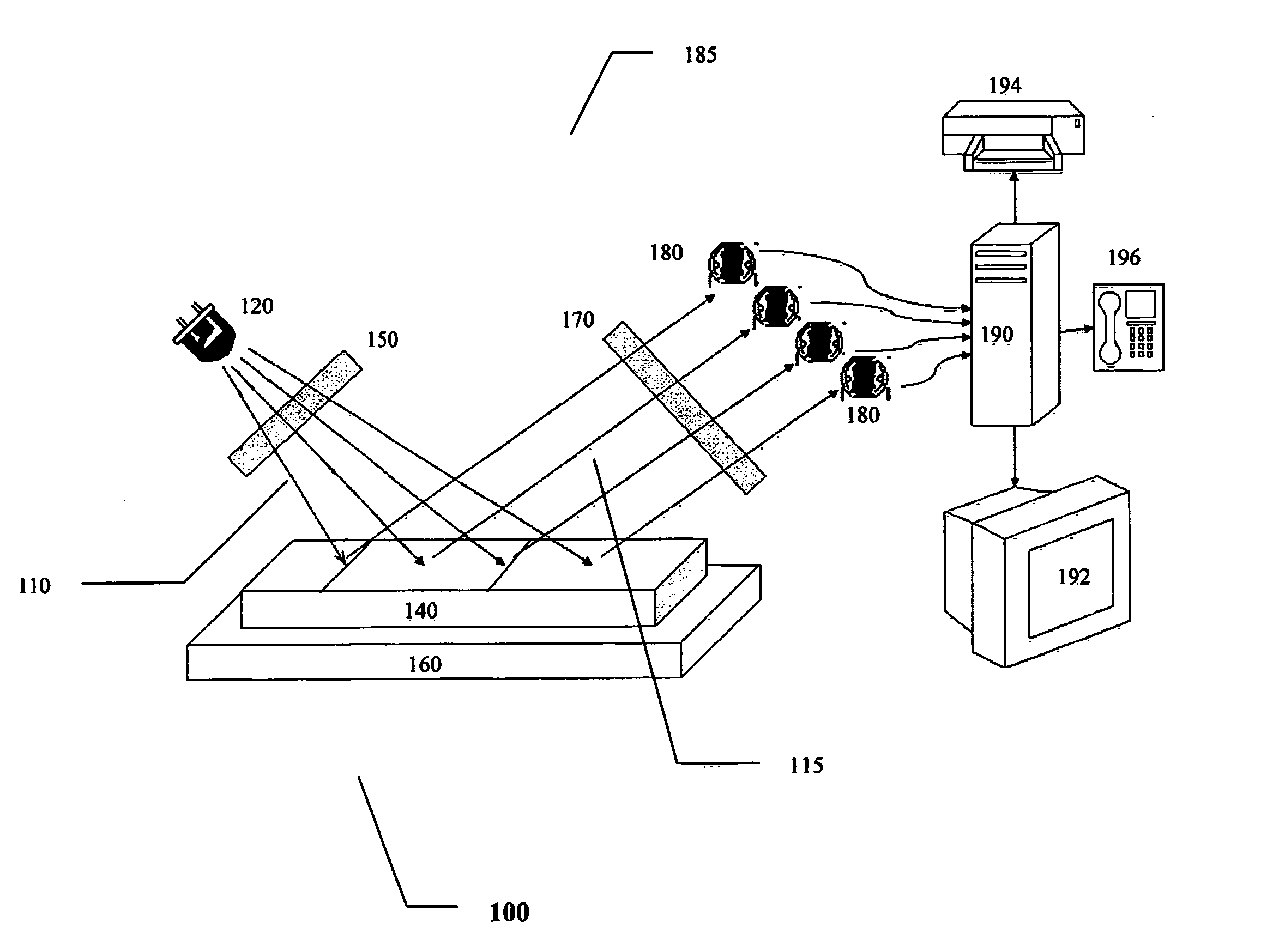
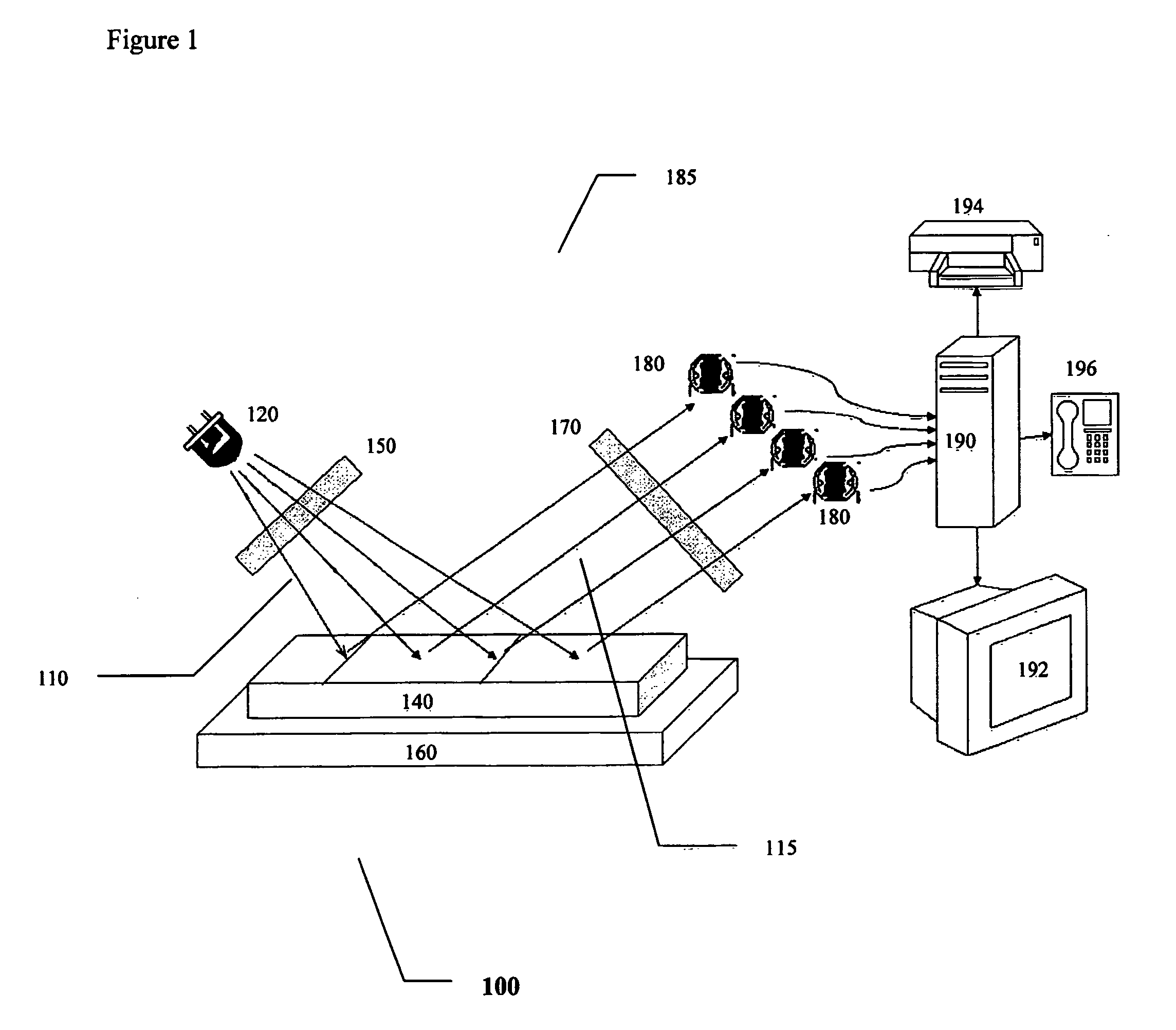
[0012] The present invention is preferably suitable for the detection and / or viewing of deposits of fluorophores on flat surfaces, such as the surface of lateral flow immunochromatography devices, by employing low-cost and low-power devices.
[0013] The device of the present invention is preferably characterized by being an inexpensive, small (“pocket-sized” or hand-held), portable device for fluorescence detection, which may optionally be powered by a battery.

Problems solved by technology

The background art also does not teach or suggest a highly portable, inexpensive yet robust and sensitive device for fluorescence detection.

Method used


Image

  • Novel device, system and method for fluorescence detection
  • Novel device, system and method for fluorescence detection
  • Novel device, system and method for fluorescence detection

Examples


example 1

Imaging of Fluorescence Employing a LED Source and Simple CCD Camera

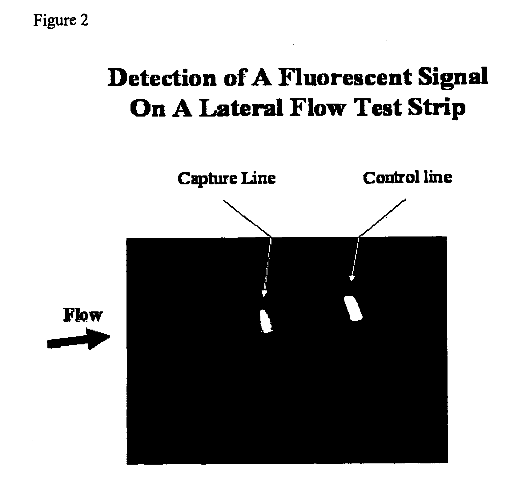
[0034] The device according to the present invention is preferably capable of detecting, imaging, capturing or otherwise sensing a fluorescent signal that is emitted from an excited fluorophore. As described above, the device is preferably capable of performing this task with a low cost and / or low power light source, and a low cost and / or low sensitivity photodetector. Non-limiting examples of such a light source and a photodetector is a LED and a non-cooled CCD camera, respectively. This Example describes the capture of an image of test results obtained with these non-limiting examples, with a sample containing a fluorophore.

[0035]FIG. 2 shows an image of actual test results for detection of a fluorescent signal on a lateral flow test strip. As shown, both a capture line 200 and a control line 210 give strong signals, with low to minimal background. The direction of flow is indicated by the arrow labeled “flow”. ...

example 2

Comparison Between Positive and Negative HIV Specimens

[0048] The device according to the present invention was further tested in this Example, to determine whether it could distinguish between positive and negative HIV specimens.

[0049] A fluorescence test system was constructed from 5 surface mounted yellow LEDs, which served as the excitation light source, and 5 photodiodes for detecting the emitted fluorescence. A red glass filter was installed in front of the photodiodes to block excitation light. The photodiodes were connected to a phase sensitive detector circuit, which translates the amount of light to counts.

[0050] HIV-1 gp41 and HIV-2 gp36 recombinant antigens were diluted in buffer and applied in a 1 mm wide line on the surface of a nitrocellulose membrane. The membrane was then cut into 5 mm wide strips, so that the antigen line traversed the strip. The strips were equipped with specimen and absorbent pads (ImmunoGold™, Orgenics LTD, Yavne, Israel) These completed strip...


PUM


Abstract

A device, system and method for portable fluorescence detection. The portable device of the present invention features a low power light, in which a wavelength range is defined as at least one wavelength of light. The light source is preferably highly energy efficient, such that a majority of the electrical power which is consumed is then converted into transmitted light. The emitted light from the excited fluorophore is then preferably detected with any low cost and low power photodetector. Although optionally a highly sensitive optical detector may be used, preferably fluorescence is detected with any light sensing device, such as a regular photodiode or a CCD (charge-coupled device) sensor for example.

Description

FIELD OF THE INVENTION [0001] The present invention relates to a novel device, system and method for fluorescence detection, and in particular, to fluorescence detection with an inexpensive, portable device. BACKGROUND OF THE INVENTION [0002] Fluorescence is used as a marker for various biological, medical and diagnostic assays. In order to be able to detect fluorescence, and hence to be able to use it as a marker for these assays, a number of components are required. First, a suitable fluorophore must be selected. The fluorophore should be excitable at a wavelength which is suitable for the given application, with a strong signal (emission of light). In addition, the fluorophore should be resistant to photobleaching, for maximum efficiency of detection. [0003] The fluorophore is then excited by the application of light of the appropriate wavelength. For excitation of the fluorescent material, a very strong light source, such as a LASER, xenon- or mercury-arc lamps or high-powered t...

Claims


Application Information

Patent Timeline
IPC IPC(8): G01N21/64G01N21/75G01N21/77G01N21/86
CPCG01N21/64G01N21/645G01N21/8483G01N33/549G01N2021/6439G01N2021/757G01N2201/0628G01N2021/7763G01N2021/7786G01N2201/0221G01N2201/0222G01N2201/0245G01N2201/062G01N2021/7759
Inventor FISH, FALKGREENBERG, ZVIFAKTOR, OURIEL
Owner INVERNESS MEDICAL SWITZERLAND GMBH
Learn More