
I-joist hole cutting apparatus

Inactive Publication Date: 2005-05-19
DAVIS JOHN D
View PDF19 Cites 12 Cited by
  • Summary
  • Abstract
  • Description
  • Claims
  • Application Information

AI Technical Summary

Benefits of technology

[0011] The flywheel configuration includes either or both of a peripheral mass agglomeration and a radial mass step-up for a maximum polar moment of inertia of the lightweight body. The peripheral mass agglomeration may be for small diameter bodies between an outer radius of a clamp cavity and the bodies' circumference. The clamp cavity may assist in fixing the groove cutting elements. With increasing body diameter, the peripheral mass agglomeration becomes more prominent within the radial boundaries of the rim. The radial mass step-up is for small diameter bodies mainly along an outward clamp cavity radius.
[0012] With increasing body diameter, the connecting structure may feature increasingly distinct spokes connected at a central portion. The radial mass step-up becomes thereby more prominent between the connecting structure and the rim.

Problems solved by technology

At the same time, sudden tool locking poses an increasing risk for excessive operational torque peaks that may rip the power drill out of the operator's hands.
Also with increasing diameter and for a limited feasible operational torque commonly associated with a hand held power drill, the cutting force of the cutting members may be insufficient to continuously remove material from the cutting groove with a circumferentially continuous cutting member as are common in prior art hole saws.
In addition, saw dust may clog up the cutting members hampering the cutting action while increasing the friction in the cutting groove.
Further more, circumferentially continuous cutting members make prior art hole saws increasingly instable with increasing cut diameter limiting their operational speed and requiring precise perpendicular orientation to the surface where the hole is to be cut.
Both limited operational speed and precise orientation are difficult to maintain with a handheld power drill especially at construction sites where holes may have to be cut at overhead locations.

Method used


Image

  • I-joist hole cutting apparatus
  • I-joist hole cutting apparatus
  • I-joist hole cutting apparatus

Examples


first embodiment

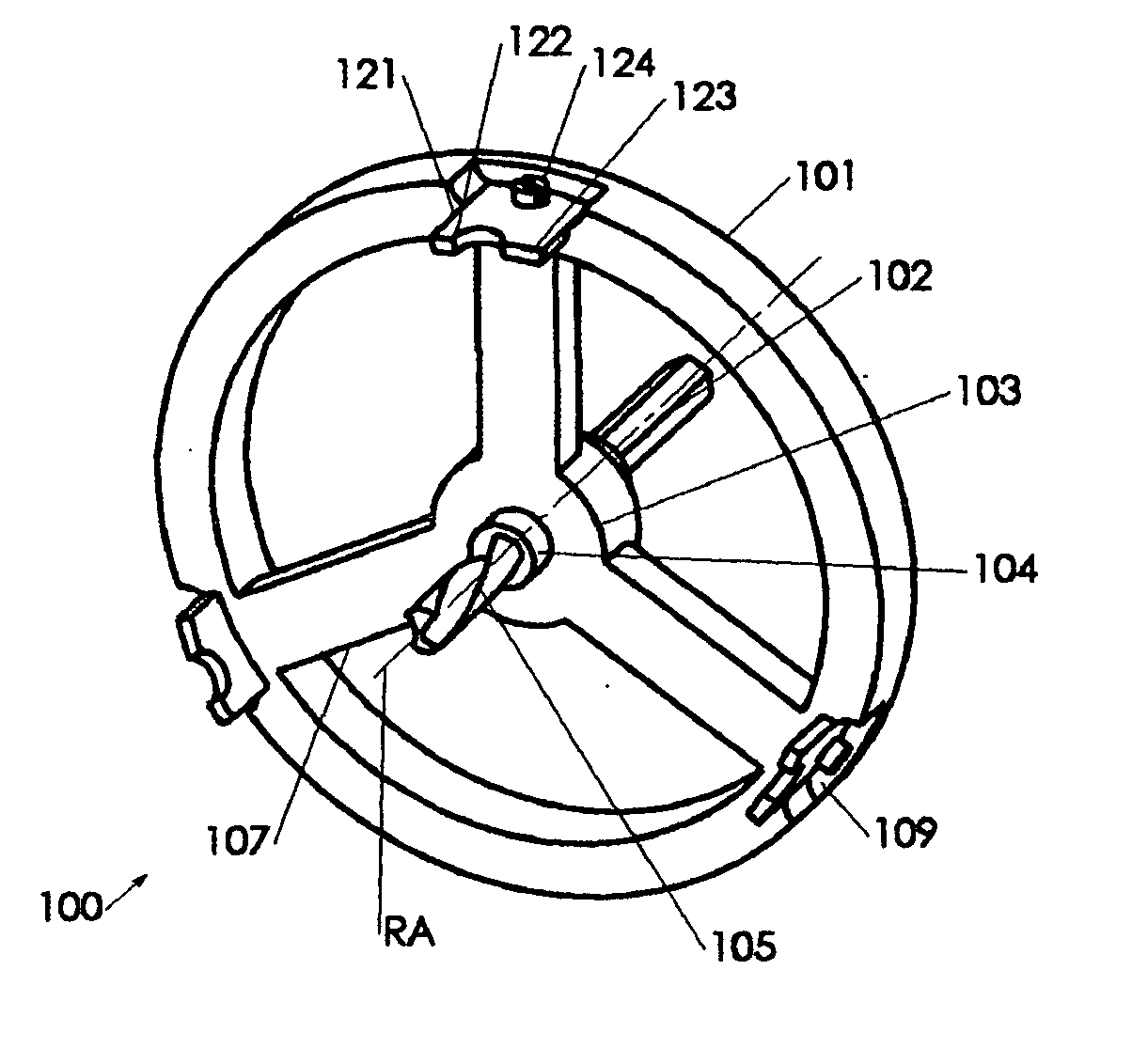
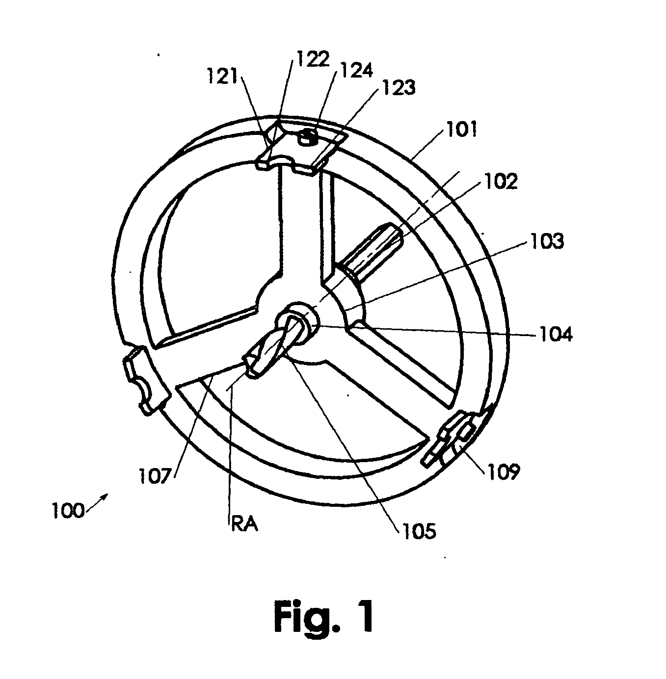
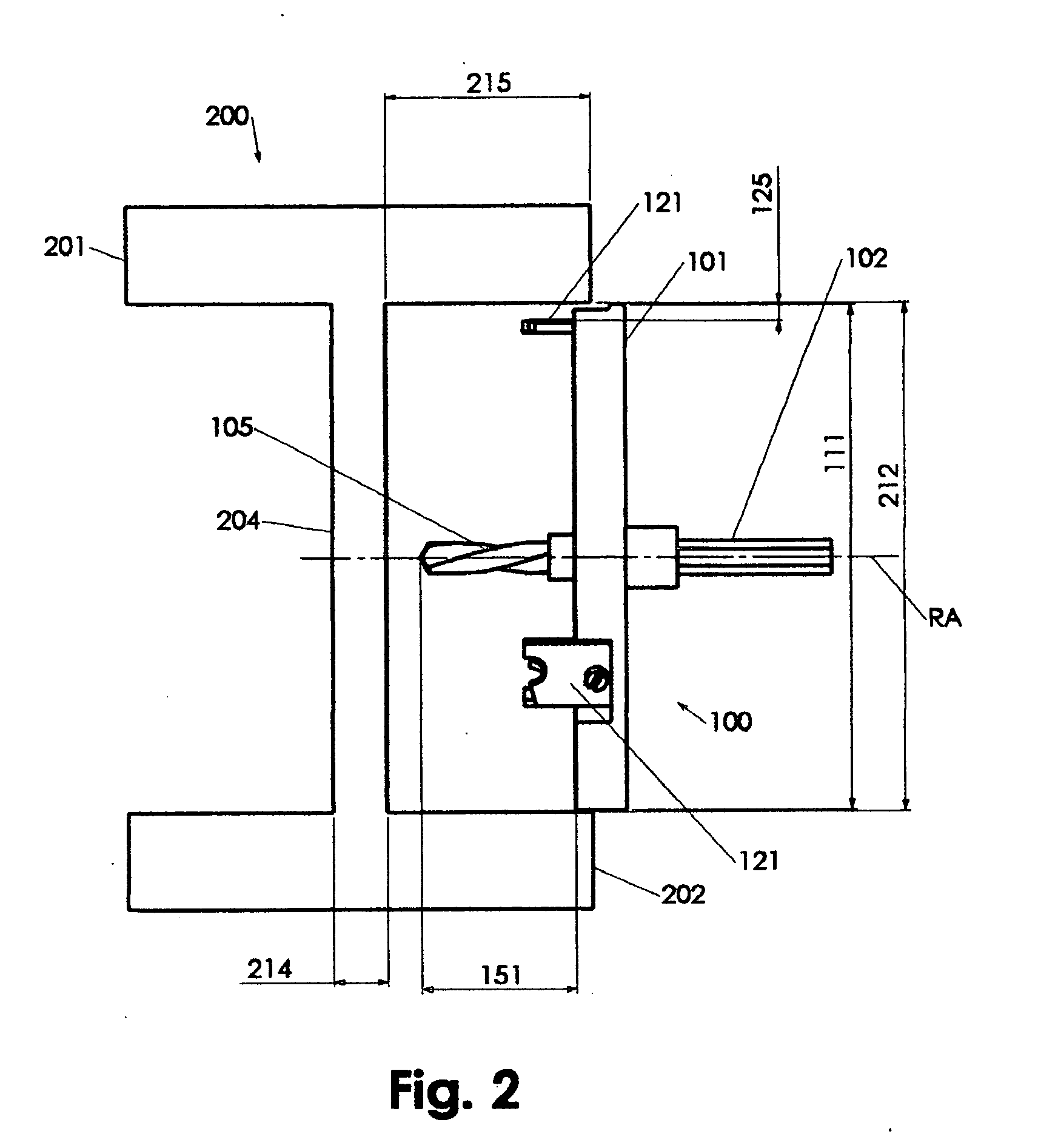
[0042] In the invention depicted in the FIGS. 1-3, the circular circumference 111 is substantially continuous, which warrants a smooth sliding of the rim 101 against adjacent chords 201, 202 during cutting operation. In context with the present invention, the substantially continuous circular circumference 111 pertains to the fact that a projection of the circular circumference 111 in axial direction renders a substantial continuous circle, despite recessing cavities 109.

second embodiment

[0043] In the invention depicted in the FIGS. 4-6, the circular circumference 311 has s substantially continuous surface, which means that all main outside boundary edges of the continuous surface are substantially circular and substantially concentric. Cap screws 324 may be accessible through radial rim openings that are not considered as outside boundary edges due to their insignificantly small diameters. The substantially continuous surface provides increased operational safety preventing inadvertent radial thump in case of premature rotation of the apparatus prior to operational positioning of the apparatus 300.

[0044] An additional safety aspect is the fact that the groove cutting members 121 are fixedly held in cavities 309 that are finite in other than axial direction. Particularly, the cavities 309 are finite in direction radial away from the axis of rotation. Under extreme conditions, where the attachment of the groove cutting members 121 may suffer from impact or the like, ...


PUM

PropertyMeasurementUnit
Thicknessaaaaaaaaaa
Angular velocityaaaaaaaaaa
Weightaaaaaaaaaa

Abstract

A hole saw for cutting standardized holes in the web portion of an I-joist features a light weight saw body having a flywheel configuration and preferably three inserted cutting blades fixed within clamp cavities in an offset to the circumference, which is dimensioned in accordance to standard web heights. The flywheel configuration provides for smooth operation at high rotational speeds in combination with intermittent actuation of the circumferentially arrayed cutting blades.

Description

CROSS REFERENCE [0001] The present application is a Continuation In Part of the U.S. application of the same title and same Inventor, application Ser. No. 10 / 788,669, which claims priority to the Provisional Application No. 60 / 451,225 filed Feb. 28, 2003. The present application cross references the concurrently filed application of the same inventor titled “Quick release arbor”, Attorney Docket No. MMC1051US, which is hereby incorporated by reference.FIELD OF INVENTION [0002] The present invention relates to hole saws. Particularly, the present invention relates to hole saws for cutting holes in a in comer regions with spacing requirements such as a web portion of an I-joist. BACKGROUND OF INVENTION [0003] I-joists are structural elements increasingly utilized in architectural constructions and the like. I-joists are beams that have an I like profile to provide maximum stiffness and strength while keeping its weight to a minimum. I-joists are commonly fabricated in a number of dime...

Claims


Application Information

Patent Timeline
IPC IPC(8): B23B51/04
CPCY10T408/89B23B51/0433B23B51/0426
Inventor DAVIS, JOHN D.
Owner DAVIS JOHN D
Learn More