Power window driving apparatus

a driving apparatus and power window technology, applied in the direction of motor/generator/converter stopper, dynamo-electric converter control, instruments, etc., can solve the problems of excessive load applied to the obstacle, inability to detect obstacles, and extremely small motor curren

Inactive Publication Date: 2005-05-19
YAZAKI CORP
View PDF2 Cites 7 Cited by
  • Summary
  • Abstract
  • Description
  • Claims
  • Application Information

AI Technical Summary

Benefits of technology

[0007] It is therefore an object of the present invention to provide a power window driving apparatus which can prevent the occurrence of erroneous stopping of a driving motor immediately after the driving motor has been activated and which can ensure the detection of a seizure of an obstacle by a widow glass in the event that such a seizure actually happens.

Problems solved by technology

In the power window having the obstacle seizure preventing function, in the event that an obstacle seizure by the power window occurs immediately after the driving motor has been activated, it is not possible to detect the obstacle seizure momentarily, resulting in a case where an excessive load is applied to the obstacle.
Namely, when the driving motor is activated, a rush current flows, and the obstacle seizure detecting function does not work until the rush current disappears.
In addition, when the window glass is operated to be raised after it has been lowered and stopped once, there is generated a state where no load is applied to the driving motor immediately after the raising operation has been implemented, and there exists a time period when the motor current becomes extremely small.
In the related power window driving apparatus, the drastic increase in the current is detected, and this results in an erroneous reversal of the driving motor in which the driving motor is erroneously stopped or reversed (see JP-A-2001-20605, for example).

Method used


Image

  • Power window driving apparatus
  • Power window driving apparatus
  • Power window driving apparatus

Examples


Embodiment Construction

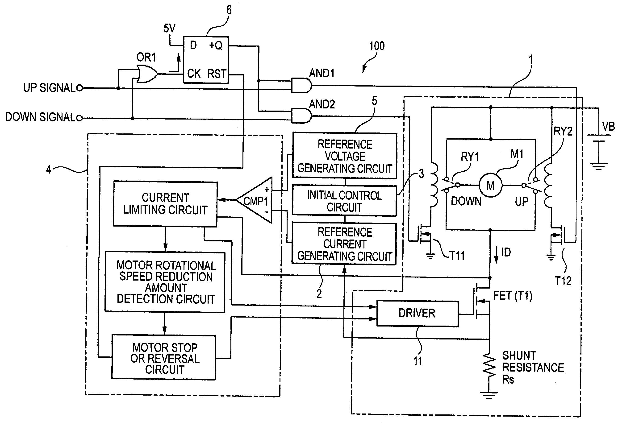
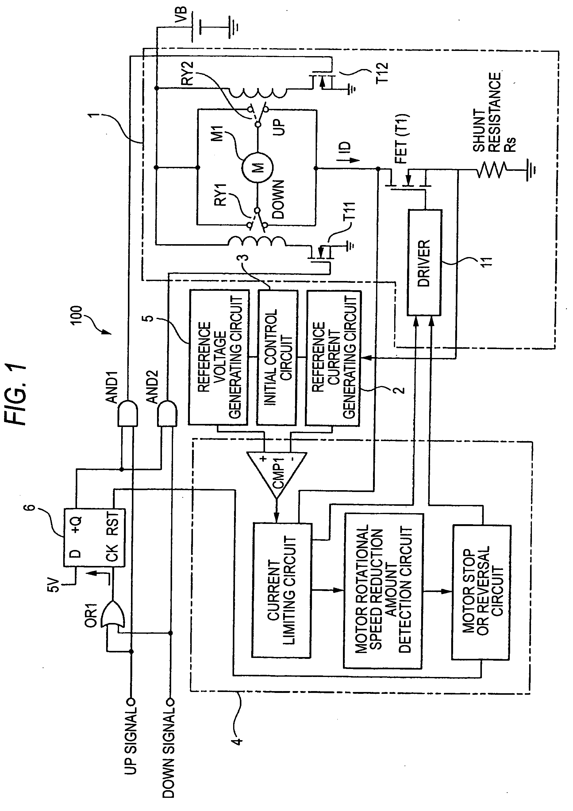
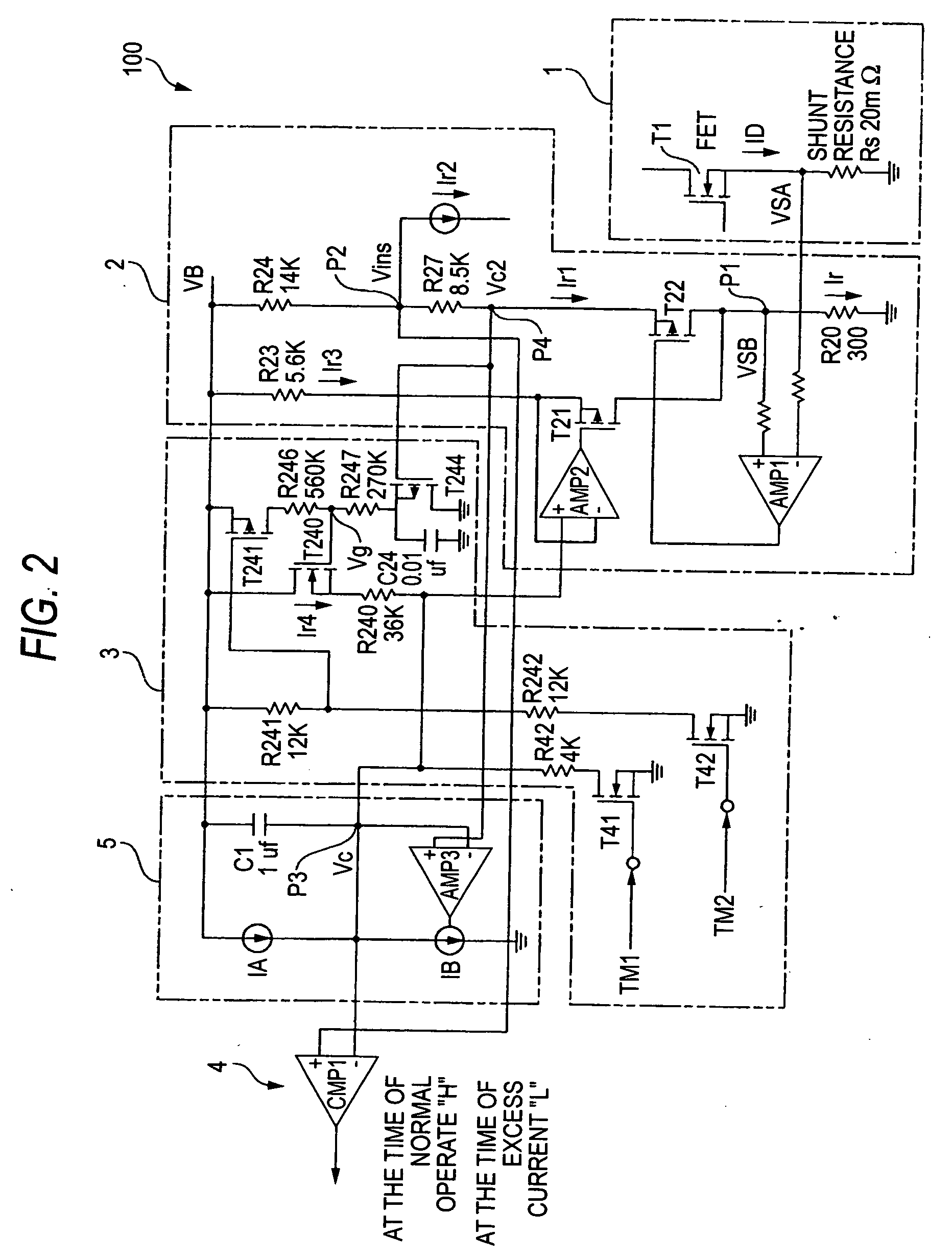
[0033] Hereinafter, an embodiment of the invention will be described based on the drawings. FIG. 1 is a block diagram showing the configuration of a power window driving apparatus according to an embodiment of the invention, and FIG. 2 is a circuit diagram (part of which is omitted) showing a specific configuration of the power window driving apparatus. As shown in FIG. 1, the power window driving apparatus 100 includes a driving circuit 1 for driving to rotate reversibly a driving motor M1 for driving a window glass, a reference current generating circuit 2, an initial control circuit 3, a reference voltage generating circuit 5 and a comparing circuit 4.

[0034] Furthermore, the power window driving apparatus 100 includes an OR circuit OR1, a flip-flop circuit 6 and two AND circuits AND1, AND2. In addition, output terminals of the AND circuits AND1, AND2 are connected to an FET (T11) and an FET (T12), respectively. When an output signal of the AND circuit AND1 results in an “H” leve...


PUM


Abstract

A power window driving apparatus includes a reference current generator which generates a reference current corresponding to a motor current. The power window driving apparatus further includes a comparator which compares the reference voltage with a comparison signal; a stopping or reversing circuit which stops or reverses the driving motor based on a comparison result by the comparator; a first timer and a second timer which measure two predetermined times from the start of activation of the driving motor; a voltage difference holder which hold a difference between the comparison signal and the reference voltage so as to be equal to or greater than a first predetermined value while the first timer is in operation; and a voltage difference reducer which reduces monotonously the difference until the difference becomes a second predetermined value while the second timer is in operation after the first timer is completed the measuring of time.

Description

BACKGROUND OF THE INVENTION [0001] The present invention relates to a power window driving apparatus for driving and controlling a power window installed in a vehicle, and more particularly to a technique for detecting with high accuracy a seizure of an obstacle when the obstacle seizure occurs at an initial stage of the driving of the power window. [0002] A power window glass is connected to a driving motor and is operated to be raised or lowered by rotating reversibly the driving motor through operation of a switch. In addition, there has been proposed and put into practical use a power window having a function to prevent a damage to an obstacle and / or a power window glass that would be caused in the event that the obstacle is seized by the power window while it is being raised by stopping and then reversing the driving motor so as to lower the power window glass. [0003] In the power window having the obstacle seizure preventing function, in the event that an obstacle seizure by t...

Claims


Application Information

Patent Timeline
Patent Type & Authority Applications(United States)
IPC IPC(8): B60J1/17E05F15/41E05F15/16E05F15/665E05F15/695H02H3/00H02H7/08H02H7/085H02P7/06
CPCE05Y2900/55H02H3/006E05F15/695H02H7/0851H02P29/02H02H7/0816E05F15/41
Inventor OHSHIMA, SHUNZOU
Owner YAZAKI CORP
Why Eureka
Try Eureka