
Holding device and cleaning tool with the holding device

Inactive Publication Date: 2005-05-19
UNI CHARM CORP
View PDF12 Cites 40 Cited by
  • Summary
  • Abstract
  • Description
  • Claims
  • Application Information

AI Technical Summary

Benefits of technology

[0012] The present invention has been worked out in view of the shortcomings in the prior art set forth above. It is therefore an object of the present invention to provide a holding device, wherein the position of a support member to which a cleaning wiper is to be attached can be changed with a simple operation and the support member can be stabilized in predetermined positions without causing unexpected turn, and a cleaning tool with the holding device.

Problems solved by technology

Therefore, it is not suitable for cleaning a variously oriented surface to be cleaned such as furniture surface.
Therefore, every time the position of the cleaning device is to be changed, there will be required such an extremely laborious operation that the rotary ring is first turned in the loosening direction of the thread for changing the position of the cleaning device and then the rotary ring is turned in the tightening direction of the thread.
In addition, the front end of the handle becomes not only thicker but also heavier due to the provision of the rotary ring.
Thus, the operating part need be strongly pushed forwardly of the handle by finger for setting the cleaning device in position, so that the operation for setting the cleaning device in position becomes laborious.
Accordingly, the operation of the rotary ring or the operating part must be done after the locking member is confronted by the recess, so that it tends to take much time to certainly fix the cleaning device in position.
That is, the cleaning tools disclosed in the two Patent Publications are not intended to support a disposable cleaning wiper, but the brush-like cleaning device for a long time use is attached to the handle.

Method used


Image

  • Holding device and cleaning tool with the holding device
  • Holding device and cleaning tool with the holding device
  • Holding device and cleaning tool with the holding device

Examples


first embodiment

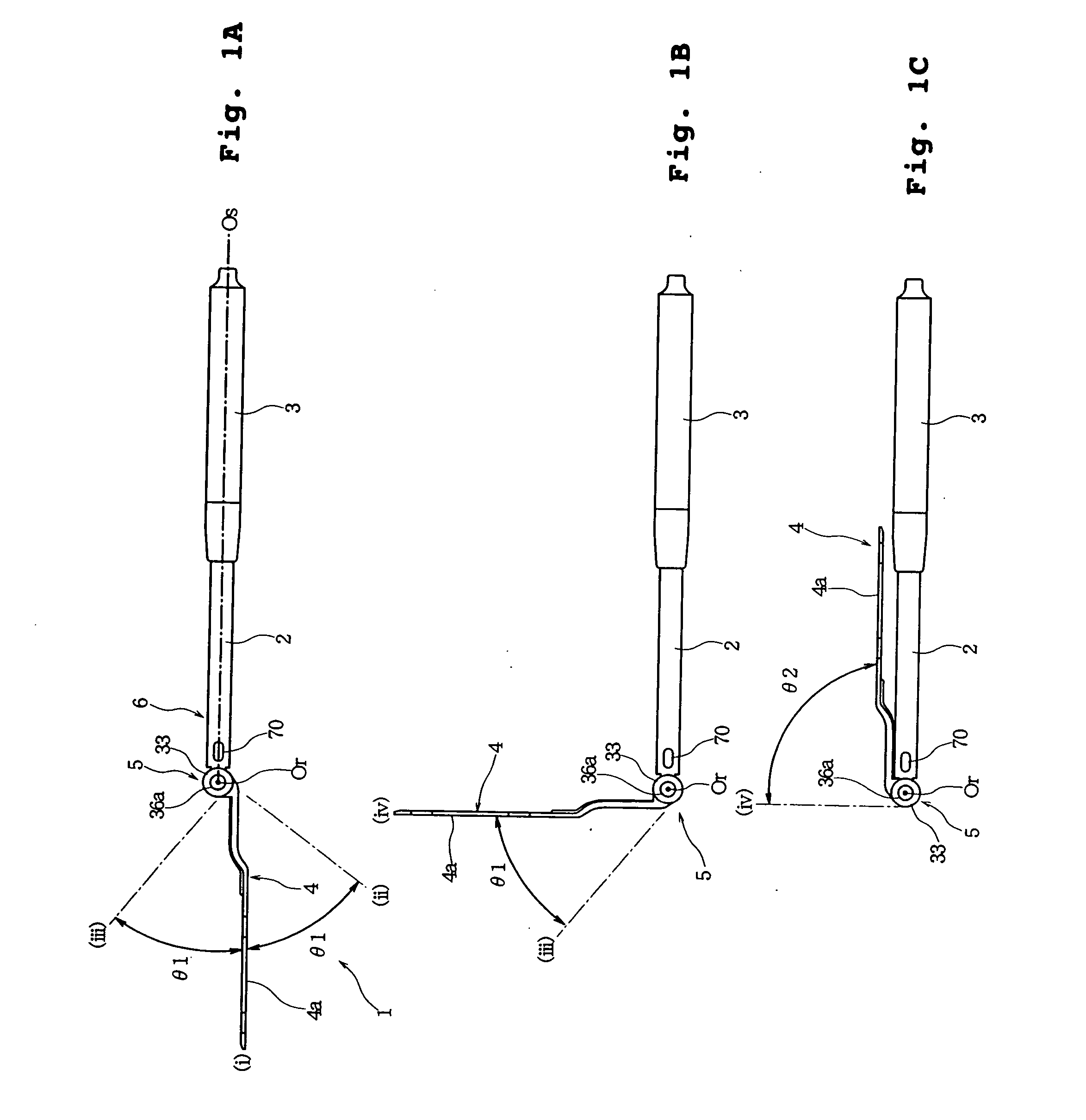
[0046]FIGS. 1A, 1B and 1C are general side views showing a holding device according to the present invention, wherein FIG. 1A shows a state where a cleaning support surface of a support member is oriented parallel with a shaft axis of a handle, FIG. 1B shows a state where the cleaning support surface is oriented perpendicular to the shaft axis of the handle, and FIG. 1C shows a state where the support member is folded back to substantially overlie the handle.

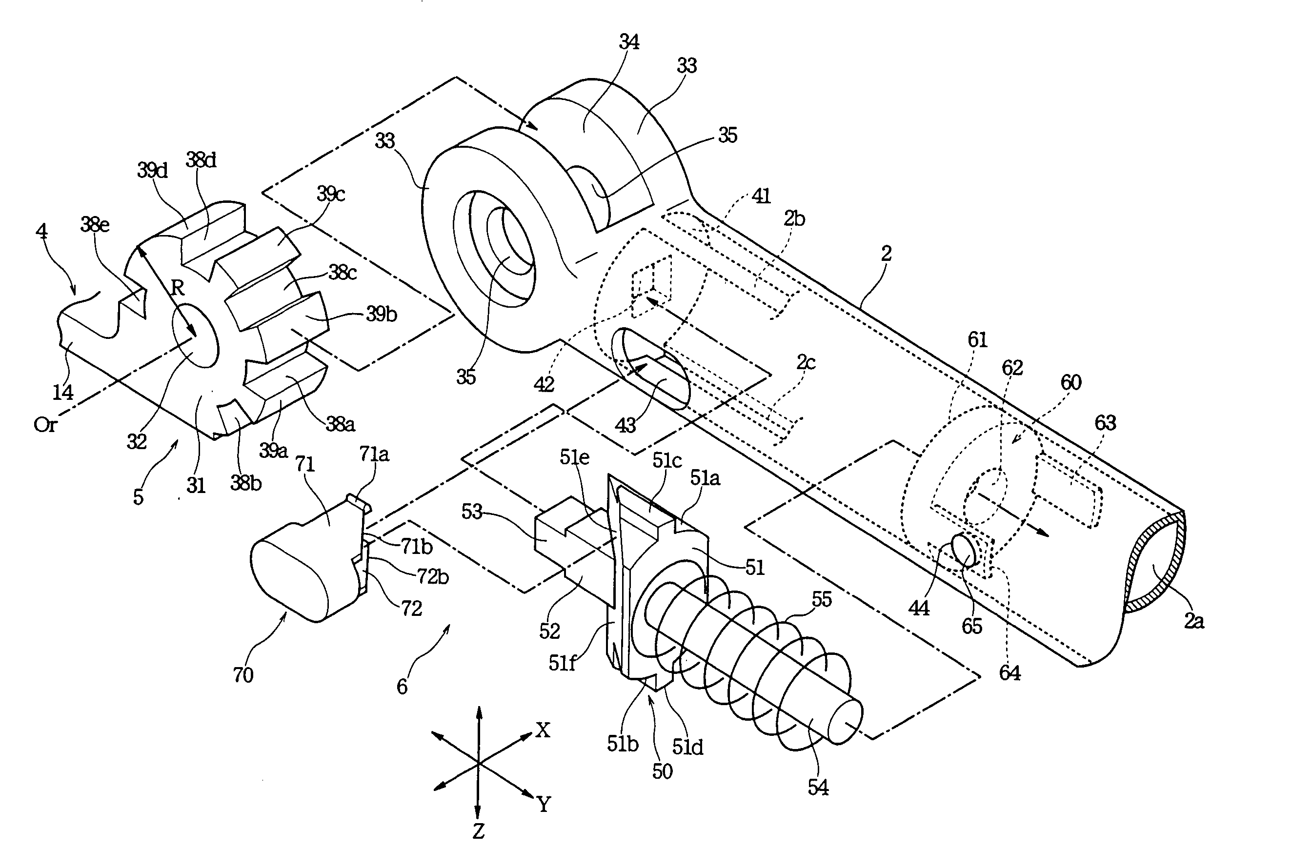
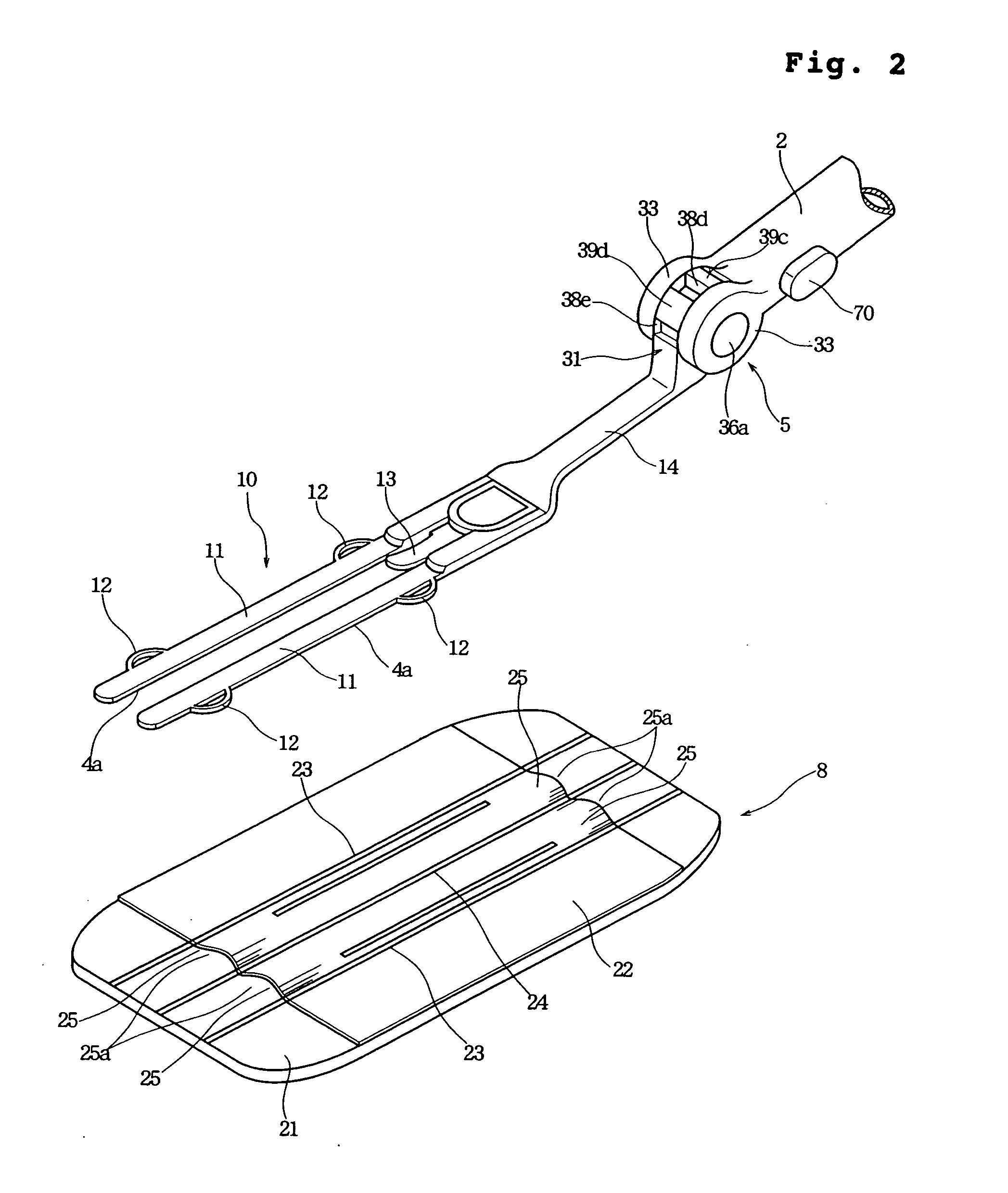
[0047]FIG. 2 is a perspective view showing a structure of the support member and a cleaning wiper to be attached to the support member; FIG. 3 is an exploded perspective view showing a pivot connection between the handle and the support member and a locking mechanism; FIG. 4 is a sectional view taken along an XY-plane, showing the pivot connection and the locking mechanism; and FIGS. 5A and 5B and FIGS. 6A and 6B are sectional views taken along a YZ-plane, showing the support member in different positions.

[0048] As shown in FIG...

second embodiment

[0095]FIG. 7 is an exploded perspective view showing a portion of a holding device 101 according to the present invention.

[0096] The holding device 101 has a locking mechanism 106 whose construction is different from that of the locking mechanism 6 of the first embodiment, but a locking member 150 provided in the locking mechanism 106 with a different support structure operates in the same manner as the locking member 50 of the locking mechanism 6. Here, the support member 4 and the pivot connection 5 have the same construction as those of the holding device 1 according to the first embodiment. In addition, the pivotal operation of the support member 4 and the operation for engaging and fixing the support member 4 in the individual positions can be performed in the same manner as described with reference to FIGS. 1A, 1B, 1C, 4, 5A, 5B, 6A and 6B. Hereinbelow, only the portions of the holding device 101 having constructions different from those of the holding device 1 will be describ...

third embodiment

[0114]FIG. 8 shows a holding device 201 according to the present invention, which is a sectional view taken along the same plane as FIG. 4.

[0115] In the holding device 201, only the locking member and the operating member have different constructions from those of the holding device 1 of the first embodiment, but the other portions have the same constructions as those of the holding device 1. Therefore, the detailed description of the portions having the same constructions as those of the holding device 1 of the first embodiment will be omitted by designating them by the common reference numerals.

[0116] In the holding device 201 of FIG. 8, a locking member 250 is provided in the mechanism housing space 2a of the handle 2. The locking member 250 has a sliding body 251 axially slidingly supported in the mechanism housing space 2a and a locking projection 253 on the front side for facing the recesses 38a, 38b, 38c, 38d and 38e and the sliding surfaces 39a, 39b, 39c and 39d provided in...


PUM


Abstract

Disclosed is a holding device including a handle and a support member pivotally connected to a front end of the handle for supporting a cleaning wiper. The support member has a pivot axis oriented in a direction crossing a shaft axis of the handle. The support member has sliding surfaces and recesses alternating with each other about the pivot axis. The handle has a locking member capable of engaging in the recesses. The locking member is movable along the shaft axis inside the handle. The locking member is provided along with a biasing member for applying a biasing force to the locking member toward the recesses and an operating member for moving the locking member against the biasing force.

Description

BACKGROUND OF THE INVENTION [0001] 1. Field of the Invention [0002] The present invention relates to a device for holding a disposable or reusable cleaning wiper and a cleaning tool constructed of the holding device and the cleaning wiper. [0003] 2. Description of the Related Art [0004] Japanese Unexamined Patent Publication Nos. 9-154791 and 9-38009 disclose cleaning tools for holding a cleaning cloth comprising nonwoven fabric and the like, in which a head for supporting the cleaning cloth is provided at a front end of a short handle or axially extendable handle that can be held with one hand. [0005] However, since the head disclosed in the above-mentioned Patent Publications is fixed in position so as not to move at the front end of the handle, the handle held with hand for cleaning a surface to be cleaned with the cleaning cloth attached to the head need be turned in various directions in accordance with the shape of the surface to be cleaned. Therefore, it is not suitable for c...

Claims


Application Information

Patent Timeline
IPC IPC(8): A47L13/10A47L13/20A47L13/24A47L13/256A47L13/38B25G1/06
CPCA47L13/20A47L13/24B25G1/06A47L13/38A47L13/256
Inventor TSUCHIYA, AKEMITANAKA, YOSHINORIFUJIWARA, MASATOSHI
Owner UNI CHARM CORP
Learn More