
Three-dimensional image display device, portable terminal device, display panel and fly eye lens

a display device and three-dimensional image technology, applied in the field of three-dimensional image display devices, portable terminal devices, display panels and fly eye lenses, can solve the problems of poor visibility, inability of the observer to recognize three-dimensional images, and inability to troublesome people, and achieve excellent visibility of color three-dimensional images

Active Publication Date: 2005-05-12
NEC LCD TECH CORP
View PDF6 Cites 45 Cited by
  • Summary
  • Abstract
  • Description
  • Claims
  • Application Information

AI Technical Summary

Benefits of technology

[0049] It is an object of the present invention to provide a three-dimensional image display device which allows an observer to recognize a color three-dimensional image with excellent visibility even in the event of rotating the three-dimensional image display device by 90° from the normal observation direction, a portable terminal device mounting the three-dimensional image display device, and a display panel and fly eye lens to be built in the three-dimensional image display device.

Problems solved by technology

However, since these methods cannot avoid being troublesome for having to wear glasses, in recent years, methods wherein wearing glasses is not necessary have been intensively studied.
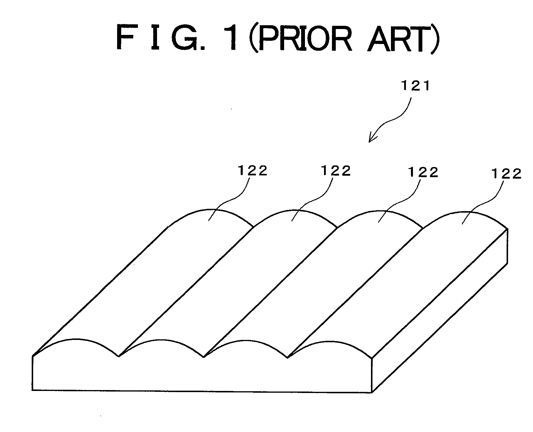
Since the parallax barrier method originally had the parallax barrier disposed between the pixel and the eye, this has led to a problem wherein the parallax barrier is conspicuous and visibility is poor.
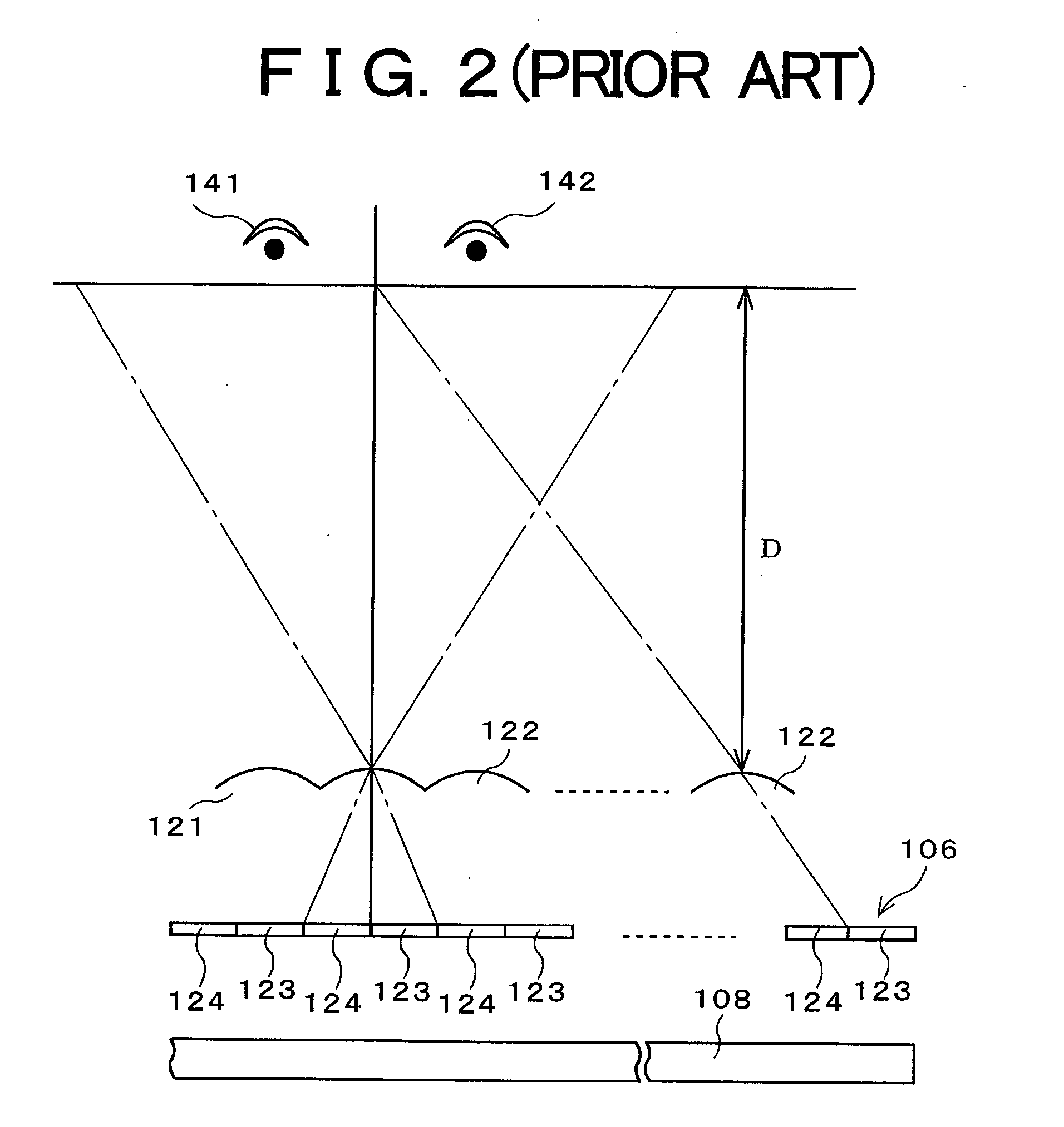
However, with the aforementioned conventional three-dimensional image display device, it is assumed that the direction for disposing a display screen is to be set in one direction as to the observer at all times. Accordingly, in the event of changing the direction of the display monitor as to the observer, it is impossible for the observer to recognize a three-dimensional image.
For example, upon the aforementioned display device being rotated by 90° in either direction from the normal direction, the observer observes the same image with both eyes, so cannot recognize a three-dimensional image.
However, the aforementioned conventional technique includes the following problems.
Hei 06-214323, in the event of displaying a color image and changing the direction for disposing the display device as to the observer, it was obvious that three-dimensional display cannot be correctly made in some cases.
Such a problem occurs not only in the lens method but also in the three-dimensional image display device using the parallax barrier method.
When this device is rotated by 90° from the normal position, the observer observes the same image with both eyes, and accordingly, cannot recognize a three-dimensional image.
As a result, in the same way as with a fly eye lens, a phenomenon occurs wherein regardless of the display device displaying a three-dimensional image, the observer cannot recognize the three-dimensional image.

Method used


Image

  • Three-dimensional image display device, portable terminal device, display panel and fly eye lens
  • Three-dimensional image display device, portable terminal device, display panel and fly eye lens
  • Three-dimensional image display device, portable terminal device, display panel and fly eye lens

Examples


first embodiment

Modification of First Embodiment

[0160] Next, description will be made regarding a modification of the first embodiment. FIGS. 22A and 22B are perspective views illustrating a handheld phone according to a modification of the first embodiment, wherein FIG. 22A illustrates a case of using a three-dimensional image display device on a normal arrangement, and FIG. 22B illustrates a case of rotating the three-dimensional image display device by 90° prior to use. As illustrated in FIGS. 22A and 22B, with the handheld phone, a three-dimensional image display device 1 is mounted so as to be rotated. The three-dimensional image display device 1 can be disposed on a normal position (hereinafter, referred to as “vertical array”) such as illustrated in FIG. 22A, and also can be disposed on a position rotated by 90° from the normal position (hereinafter, referred to as “horizontal array”) such as illustrated in FIG. 22B. For example, the three-dimensional image display device 1 is connected to a...

second embodiment

[0167] Next, description will be made regarding a second embodiment of the present invention. FIG. 24 is an optical model diagram in a case wherein a three-dimensional image display device according to a second embodiment of the present invention is disposed such that the aforementioned first direction becomes the direction of both eyes of an observer. FIG. 25 is an optical model diagram in a case wherein the three-dimensional image display device according to the second embodiment of the present invention is disposed such that the aforementioned second direction is the direction of both eyes of the observer. The present embodiment is in a case wherein magnifying power of pixels is increased compared with that in the first embodiment, the value of (e / 3) is included in the range 33 in FIG. 21. In other words, the value of (e / 3) satisfies the following Expression 60. In this case, in the event that the three-dimensional image display device is disposed such that the second direction 2...

third embodiment

[0169] Next, description will be made regarding a third embodiment of the present invention. FIG. 26 is an optical model diagram in a case wherein a three-dimensional image display device according to a third embodiment of the present invention is disposed such that the aforementioned first direction becomes the direction of both eyes of an observer, FIG. 27 is an optical model diagram in a case wherein the three-dimensional image display device according to the third embodiment of the present invention is disposed such that the aforementioned second direction is the direction of both eyes of the observer. The present embodiment is in a case wherein magnifying power of pixels is decreased compared with that in the first embodiment, the pixel magnifying projection width e / 3 in the second direction 22 satisfies the following Expression 63 as to the mean interpupillary distance. This is equivalent to the range 35 illustrated in FIG. 21. In this case, in the event that the three-dimensi...


PUM


Abstract

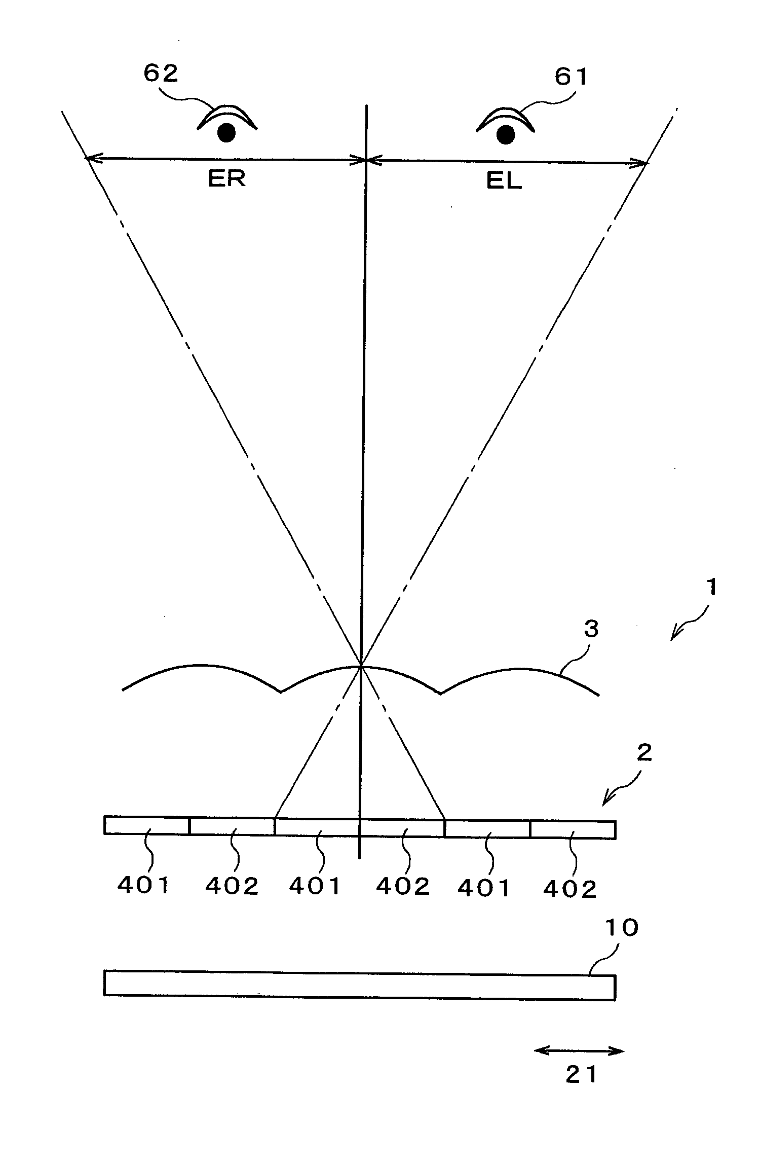
In a three-dimensional image display device for displaying color three-dimensional images, a fly eye lens, a display panel, and a light source are provided in this order from the observer side. A display panel has four pixels arrayed in a (2×2) matrix correlated with one lens element of the fly eye lens. In the event that j is a natural number, a pixel magnifying projection width e in a second direction is set in a range of the following expression according to mean interpupillary distance Y of the observers. e3≠Y2×j

Description

BACKGROUND OF THE INVENTION [0001] 1. Field of the Invention [0002] The present invention relates to a color three-dimensional image display device capable of displaying three-dimensional images, a portable terminal device mounting the three-dimensional image display device, and a display panel and fly eye lens to be built in the three-dimensional image display device, and more specifically relates to a three-dimensional image display device, portable terminal device, display panel, and fly eye lens, which are capable of stereoscopic viewing even in the event that the three-dimensional image display device is disposed not only in one direction alone but also in another direction orthogonal to this one direction. [0003] Examples of applications to which the present invention is applied include portable terminal devices such as handheld phones, PDAs, game devices, digital cameras, and digital video cameras. [0004] 2. Description of the Related Art [0005] Conventionally, study of a dis...

Claims


Application Information

Patent Timeline
Patent Type & Authority Applications(United States)
IPC IPC(8): G02B30/27G02B30/30G03B35/00H04N13/305H04N13/307
CPCG02B27/2214H04N13/0422H04N13/0409H04N13/0406H04N13/31H04N13/324H04N13/307G02B30/27H04N13/305G02B30/30
Inventor UEHARA, SHIN-ICHIIKEDA, NAOYASUTAKANASHI, NOBUAKI
Owner NEC LCD TECH CORP
Learn More