
Sensor element and method for determining ammonia

a technology of ammonia and sensor elements, applied in the direction of instruments, liquid/fluent solid measurements, electrochemical variables of materials, etc., can solve the problems of limited sensor determining of oxygen and nitrogen oxide concentration, and achieve the effect of simple sensor layout and high measuring accuracy

Inactive Publication Date: 2005-05-12
ROBERT BOSCH GMBH
View PDF7 Cites 15 Cited by
  • Summary
  • Abstract
  • Description
  • Claims
  • Application Information

AI Technical Summary

Benefits of technology

[0004] In contrast, the exemplary embodiment and / or exemplary method of the present invention is based on the object of providing a sensor element for a gas sensor and a method, which reliably ensure the determination of ammonia and, optionally, a further component in a gas mixture and may still be inexpensively manufactured.
[0005] The sensor element of the present invention and the exemplary method of the present invention, as described herein, possess the advantage that they may reliably allow the ammonia concentration of a gas mixture to be determined. To this end, a potential, at which the ammonia present in the gas mixture is oxidized, is advantageously applied to a measuring electrode or an auxiliary electrode of the sensor element. In the process, nitrogen monoxide and, to a secondary extent, nitrogen dioxide, dinitrogen monoxide, and, in some instances, further nitrogen oxides are formed as oxidation products. If a potential, at which ammonia is oxidized, is applied to a measuring electrode, then the ammonia concentration of the gas mixture may be determined in a simple manner by simply determining the pump current flowing between the measuring electrode and a counterelectrode.
[0007] Advantageous further refinements and improvements of the sensor element and method are described herein. Thus, it is, for example, believed to be advantageous when the sensor element has two measuring electrodes in its interior; the two measuring electrodes each being preceded by an auxiliary electrode, at which the ammonia contained in the gas mixture is oxidized. A further auxiliary electrode, at which nitrogen oxides already contained in the gas mixture from the start are decomposed, is placed in front of at least one of the two auxiliary electrodes. Such a sensor element advantageously allows the sum of the nitrogen-oxide amount resulting from the oxidation of ammonia and the nitrogen oxide amount already present in the gas mixture from the start to be determined, using the first measuring electrode, and the concentration of nitrogen oxides formed exclusively during the oxidation of the ammonia contained in the gas mixture to be determined, using the second measuring electrode. The calculation of the difference of the two measuring signals allows the concentration of ammonia and the concentration of the nitrogen oxides already contained in the gas mixture from the start to be determined in an exact manner, independently of each other.
[0009] In a second time interval, only oxygen is reduced and ammonia oxidized at at least one auxiliary electrode, so that ammonia-oxidation products contained in the gas mixture may reach the measuring electrode in the form of nitrogen oxides. In this manner, the sum of the nitrogen oxides already present in the gas mixture and the nitrogen oxides forming during the oxidation of ammonia is determined at the measuring electrode, in the second time interval. The concentration of ammonia and the concentration of nitrogen oxides contained in the gas mixture from the start may be determined, from the calculation of the difference of the measuring signal in the second time interval minus the measuring signal in the first time interval. This allows a particularly simple sensor layout, while simultaneously having high measuring accuracy.

Problems solved by technology

However, this sensor is limited to determining the concentration of oxygen and nitrogen oxides.

Method used


Image

  • Sensor element and method for determining ammonia
  • Sensor element and method for determining ammonia
  • Sensor element and method for determining ammonia

Examples


Embodiment Construction

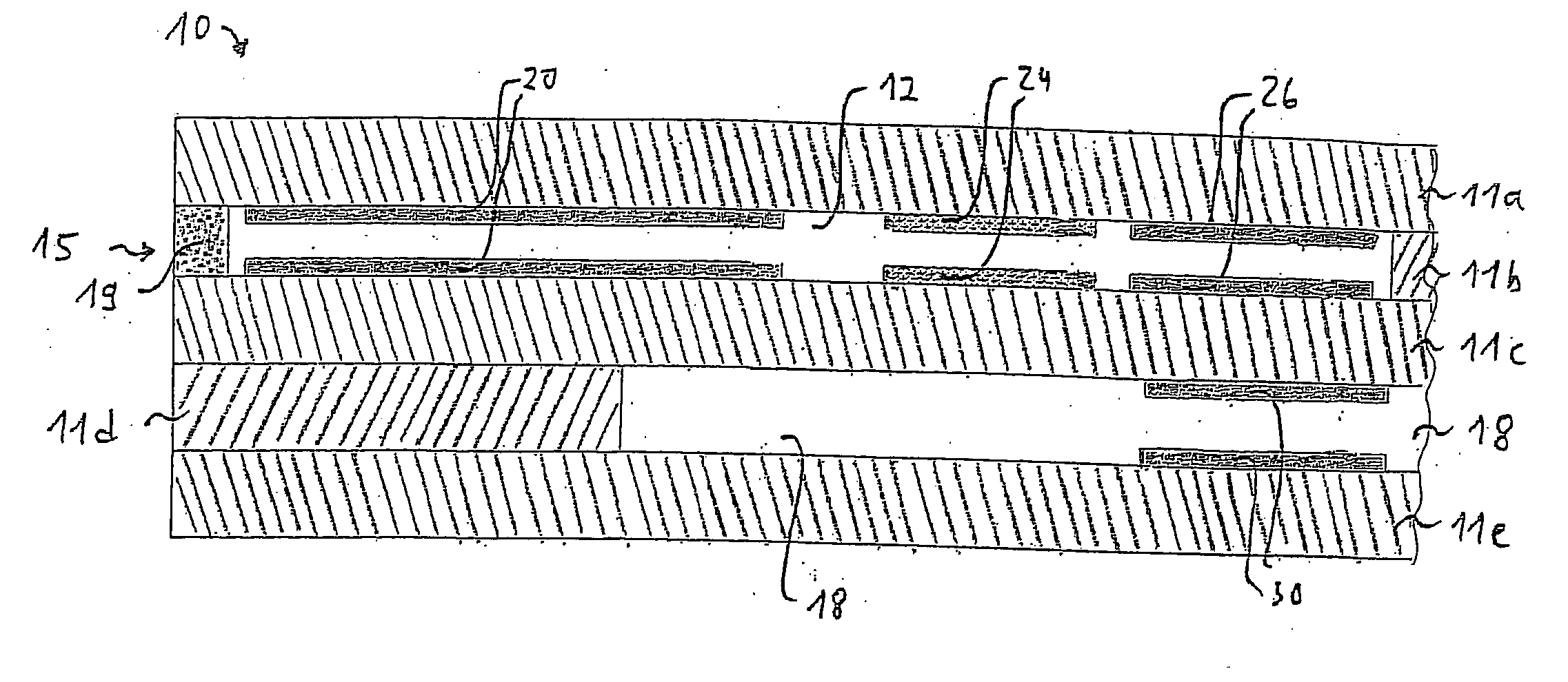
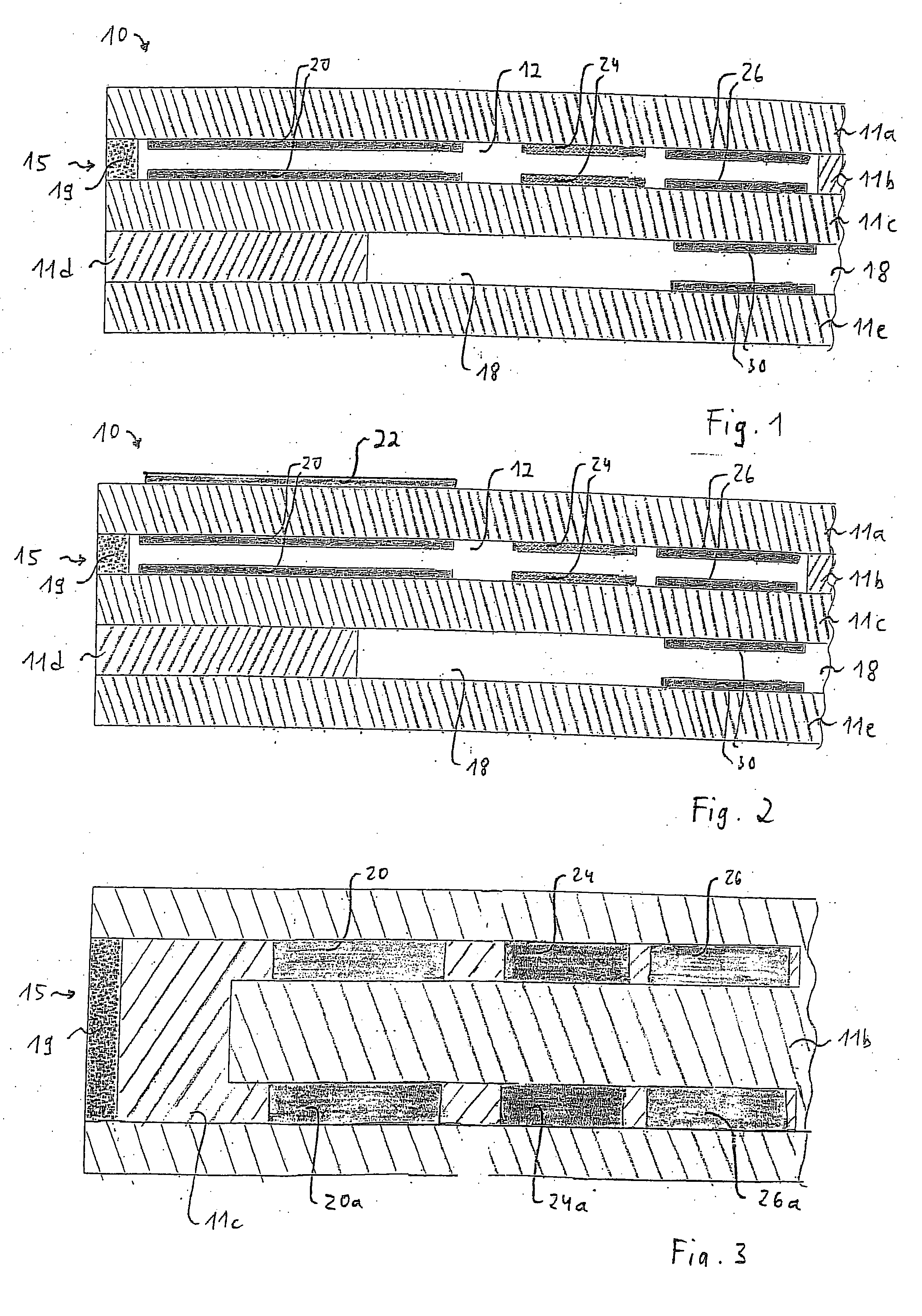
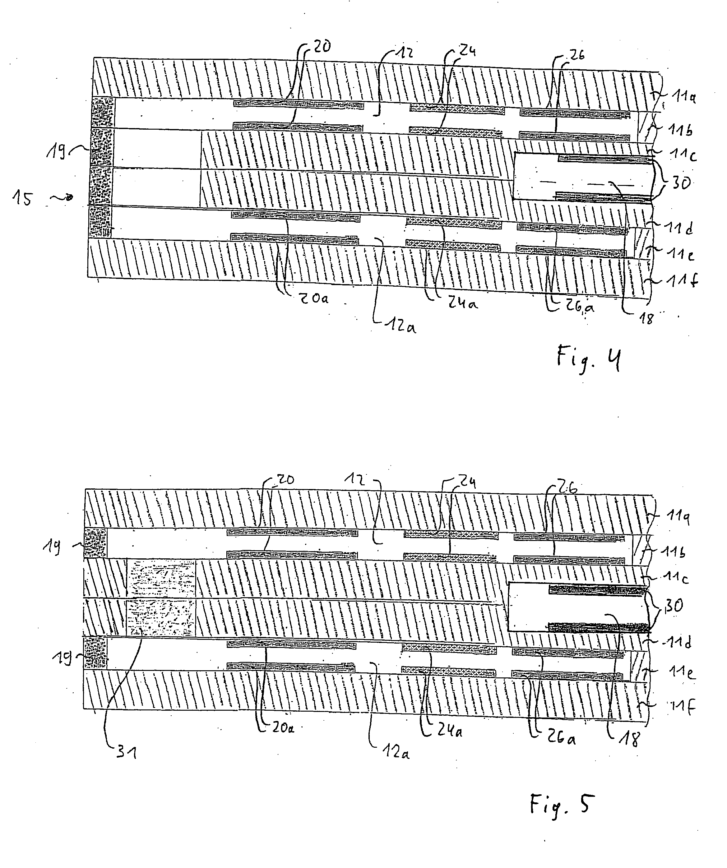
[0015]FIG. 1 shows a schematic of the structure of a first specific embodiment according to the present invention. Reference numeral 10 designates a planar sensor element of an electrochemical gas sensor, which is used for determining ammonia and, optionally, a further component of a gas mixture, which may be in exhaust gases of combustion engines. The sensor element has a plurality of oxygen-ion-conducting, solid-electrolyte layers 11a, 11b, 11c, 11d, and 11e, which are designed, for example, as ceramic foils and form a planar ceramic body. They are made of a solid-electrolyte material that conducts oxygen ions, such as ZrO2 stabilized or partially stabilized with Y2O3.

[0016] The integrated form of the planar ceramic body of sensor element 10 is produced in a manner known per se, by laminating together the ceramic foils printed over with functional layers and subsequently sintering the laminated structure.

[0017] Sensor element 10 contains, for example, an inner gas compartment 12...


PUM

PropertyMeasurementUnit
operating temperatureaaaaaaaaaa
concentrationaaaaaaaaaa
timeaaaaaaaaaa

Abstract

A sensor element of a gas sensor, which is used for determining the concentration of ammonia and, optionally, at least one further component of a gas mixture, in particular in exhaust gases of combustion engines. The sensor element includes at least one first auxiliary electrode and at least one measuring electrode positioned downstream in the flow direction of the gas mixture, which are in direct contact with the gas mixture, a signal generated by the measuring electrode being used at least intermittently for determining the concentration of ammonia. A potential, at which ammonia contained in the gas mixture is oxidized, is applied at least intermittently to the first auxiliary electrode or the measuring electrode.

Description

FIELD OF THE INVENTION [0001] The present invention relates to a sensor element of a gas sensor and a method for determining the concentration of ammonia and, optionally, a further component of a gas mixture. BACKGROUND INFORMATION [0002] In the course of increasingly stringent environmental guidelines, the sensory system in the region of combustion-engine exhaust gases is becoming increasingly important. In this context, particularly gas sensors based on solid electrolyte are used, which identify the gaseous components to be detected in the exhaust gas in a highly selective manner. In combustion engines operated with a hyperstoichiometric amount of air, the formation of nitrogen oxides is increased. In order to be able to remove them from the exhaust gas, emission-control systems based on the addition of reductive substances to the exhaust system are important. For example, ammonia or ammonia-releasing substances such as urea are used for this purpose. Since besides the emission of...

Claims


Application Information

Patent Timeline
Patent Type & Authority Applications(United States)
IPC IPC(8): G01N27/407G01N31/00
CPCG01N31/005G01N27/4074
Inventor OCHS, THORSTENSCHICHLEIN, HELGETHIEMANN-HANDLER, SABINESCHUMANN, BERND
Owner ROBERT BOSCH GMBH
Learn More