
Elasticated materials

a technology of elastic and carrier material, applied in the field of elasticated materials, can solve the problems of not always being able to combine elastic and stiff carrier material of low load force, and achieve the effects of large width, high bending stiffness, and small distance (length)

Inactive Publication Date: 2005-05-05
THE PROCTER & GAMBLE COMPANY
View PDF98 Cites 93 Cited by
  • Summary
  • Abstract
  • Description
  • Claims
  • Application Information

AI Technical Summary

Benefits of technology

[0017] The specific new bonding pattern is such that there are large open areas between the bonding areas. In a preferred embodiment, the bonding areas are separated, i.e. not connected to one another, typically such that the open areas between the bonding areas are not limited (by bonding) in the direction that is more or less orthogonal to the direction of stretch. This allows the ridges, as mentioned above, to form without being forced into a pillow-like structure, as would take place with the bonding patterns known in the art (such as the known Omega bonding pattern, described in US 2002 / 0119722).
[0018] A second embodiment of the invention relates to an elasticated carrier material as defined above under a) and b) above, but whereby: c) the bonding pattern has (i) a width (X) and a length (Y); and (ii) one or more bonding areas, each area comprising repeating bonding shapes, connected to one another, each shape having a width Xs, and a length Ys, whereby the ratio of Ys to Xs is less than 0.1 and more preferred less than 0.05.
[0019] In one embodiment, the pattern may be an Omega pattern, which is however significantly different to the Omega pattern used in the art, since it has a much larger width and a much smaller distance (length) between the repeating bonding shapes (Omega's).
[0020] Typically, high basis weight carrier materials have a high bending stiffness. Thus, alternatively, the elasticated materials may be defined as above, with the exception that the carrier material is defined by the meltblown content in the material, namely being basis a meltblown content of at least 5 gram per m2, or even 10 gram per m2 or more, or even 15 grams per m2 or more, and the smallest distance (D; in mm) between two subsequent bonding areas is at least [0.6 mm+M*0.01*(mm*m2 / g)+M2*0.005*mm*(m2 / g)2], where M is the meltblown content in g / m2.
[0021] If the carrier material is a laminate of layers of materials, whereof more than one layer comprises meltblown fibres, then the meltblown content referred to above is the sum of the meltblown content values of the layers containing meltblown fibres.
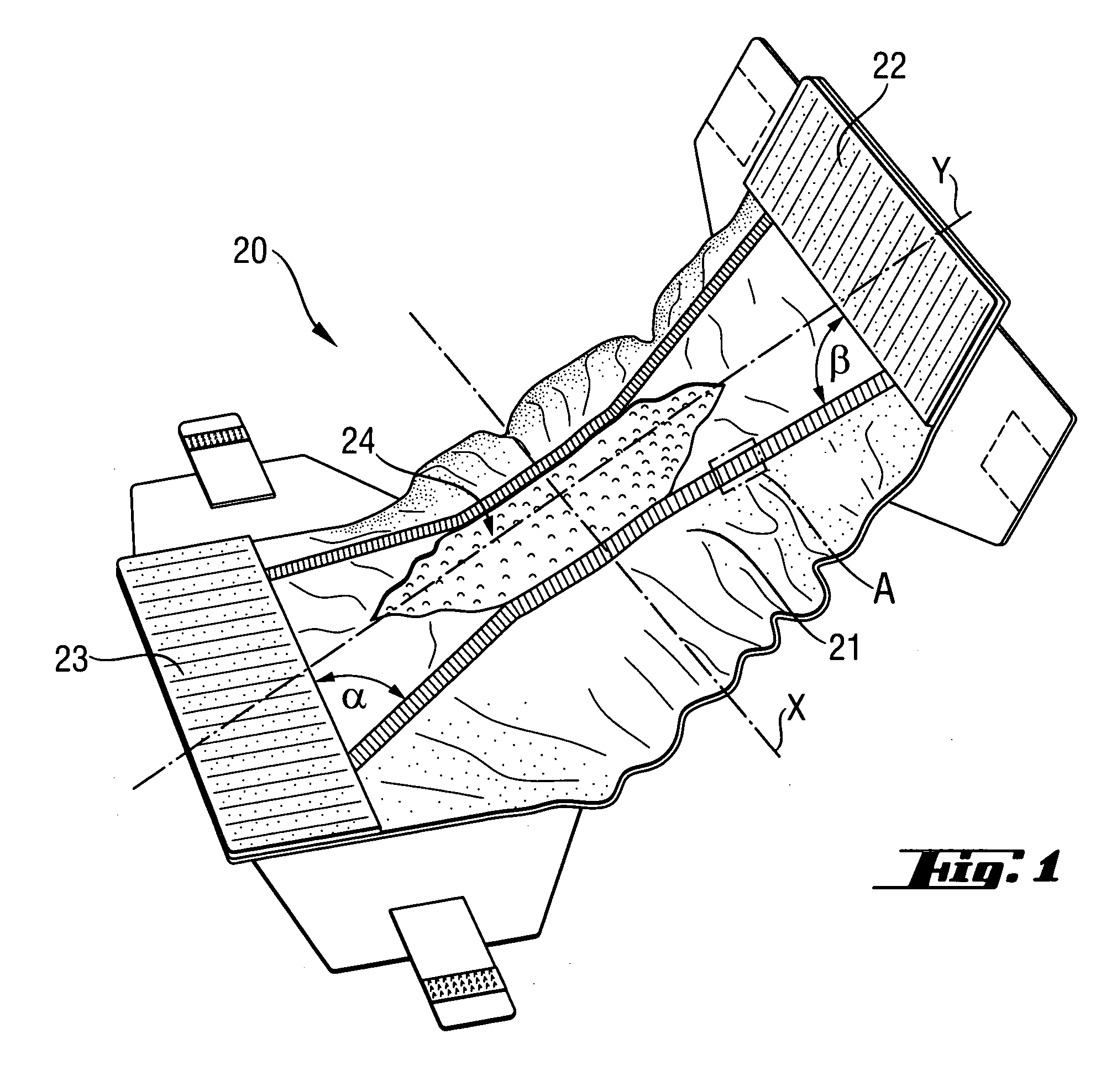
[0022] The invention also provides absorbent articles, such as diapers and / or training pants, comprising the elasticated material. In a preferred embodiment, the elasticated material is, or forms part of, the anal / vaginal cuff or topsheet, preferably such a cuff or topsheet with one or more large openings to receive fecal matter, as described herein.

Problems solved by technology

However, the inventors have found that the combination of low load force elastics and stiff carrier (topsheet) material is not always possible: the low force elastics are typically not capable to contract the stiff carrier material in the required way.

Method used


Image

  • Elasticated materials
  • Elasticated materials
  • Elasticated materials

Examples


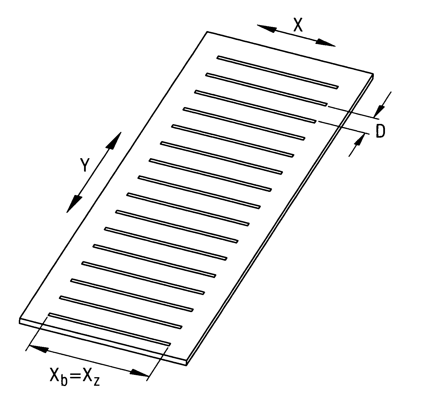
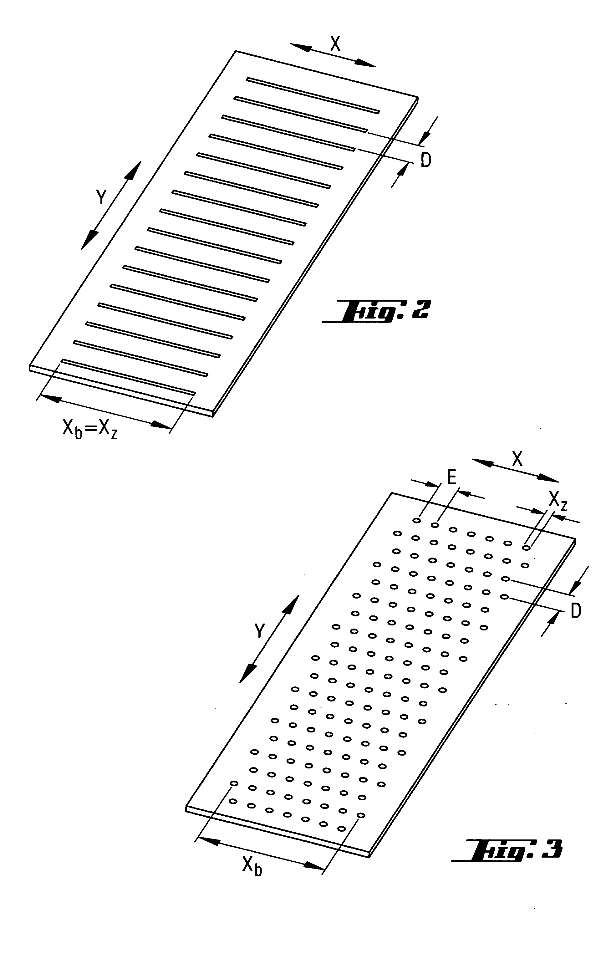
first embodiment

[0034] In the invention, the bonding pattern comprises a multitude of separate bonding areas, each with a width Xb. Each bonding area then extends substantially in the width (X) direction.

[0035] In this embodiment, the multitude of bonding areas are separated from one another and they are positioned (extend) substantially along the length (direction) of the carrier material, as for example may be seen in FIG. 2.

[0036] Each bonding area comprises one or more separate bonding zones, (extending) along substantially the width (X) direction, said zone(s) having a width dimension Xz, and a second dimension Yz, preferably substantially parallel to X.

[0037] For example, the bonding area may consist of (and thus be equivalent to) one single bonding zone, for example in the form of a single bonding line, typically substantially parallel to X.

[0038] Alternatively, the bonding area may also comprise a number of bonding zones, for example a number of bonding dots or lines. In a preferred embo...

second embodiment

[0040] In the invention, the smallest distance (D) (in mm) between two subsequent bonding areas is at least 0.6 mm+M*0.01*(mm*m2 / g)+M2*0.005*mm*(m2 / g)2, where M is the meltblown content in g / m2. Preferably D is at least 0.9 mm+M*0.01+M2*0.01, or even more preferably D is at least 1.2 mm+M*0.02+M2*0.01.

[0041] A bonding zone may optionally be formed from repeating wave-shaped bonding units, each having an amplitude A. Thus, the bonding zone then contains repeating units that are connected to one another in the width direction, each of said repeating units having a width dimension Xu.

[0042] Then, it is important that the ‘open’ area between the bonding areas, i.e. the area where there are no bonding areas, is still large, namely such that (when repeating wave-shaped units are present), the amplitude A of each unit is less than 0.5×(D), preferably less than 0.4×(D) or even less than 0.3×(D).

[0043] Thus for example, a bonding area may comprise one wavy-line, comprising a number of conn...


PUM

PropertyMeasurementUnit
elastic load forceaaaaaaaaaa
elastic forceaaaaaaaaaa
back CD forceaaaaaaaaaa

Abstract

This invention relates to an elasticated materials comprising a stiff carrier material that is satisfactorily elasticated with one or more elastic strands with a low load force, due to the use of a specific bonding pattern, with specific bonding areas. The bonding areas are typically separate bonding areas positioned on separate intervals along the length direction of the carrier material, whereby each bonding area comprises one or more separate bonding zones, extending in the width (X) direction. The invention also relates to absorbent articles comprising this elasticated material and processes for making the elasticated material.

Description

FIELD OF THE INVENTION [0001] This invention relates to an elasticated materials comprising a stiff carrier material that is satisfactorily elasticated with one or more elastic strands with a low load force, due to the use of a specific bonding pattern, with specific bonding areas. The invention also relates to absorbent articles comprising this elasticated material and processes for making the elasticated material. BACKGROUND OF THE INVENTION [0002] Absorbent articles such as diapers comprise normally one or more components that are elasticated, such as the leg cuffs or waistband. Other absorbent articles, that incorporate an elasticated component, are diapers that have a so-called elasticated anal and / or vaginal cuff. Such cuffs may for example be formed by a topsheet that has one or more large opening(s) to receive fecal material, and guide it to a void space, the topsheet having elastic strands along the opening(s) in the topsheet in order to position the aperture correctly agai...

Claims


Application Information

Patent Timeline
Patent Type & Authority Applications(United States)
IPC IPC(8): A61F13/15D03D15/56
CPCA61F13/15203A61F13/15593A61F13/495A61F13/4902A61F13/15699Y10T442/643Y10T442/601
Inventor MUELLER, JOERGHIPPE, MATTHIAS KONRADMARTYNUS, CORNELIA BEATESCHMIDT, MATTIASBIRKMANN, SIMONEGEILICH, RALF
Owner THE PROCTER & GAMBLE COMPANY
Learn More