
Characteristic measurement system for a digital modulation signal transmission circuit

a digital modulation and transmission circuit technology, applied in data switching networks, orthogonal multiplexes, amplitude demodulation, etc., can solve the problems of difficult to measure a transmission system, few opportunities for stopping its operation, and insufficient accuracy and cos

Inactive Publication Date: 2005-05-05
AKITA YONEO
View PDF7 Cites 13 Cited by
  • Summary
  • Abstract
  • Description
  • Claims
  • Application Information

AI Technical Summary

Benefits of technology

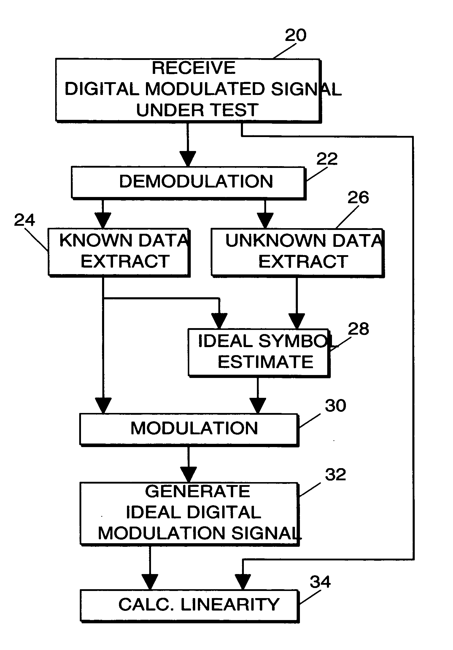
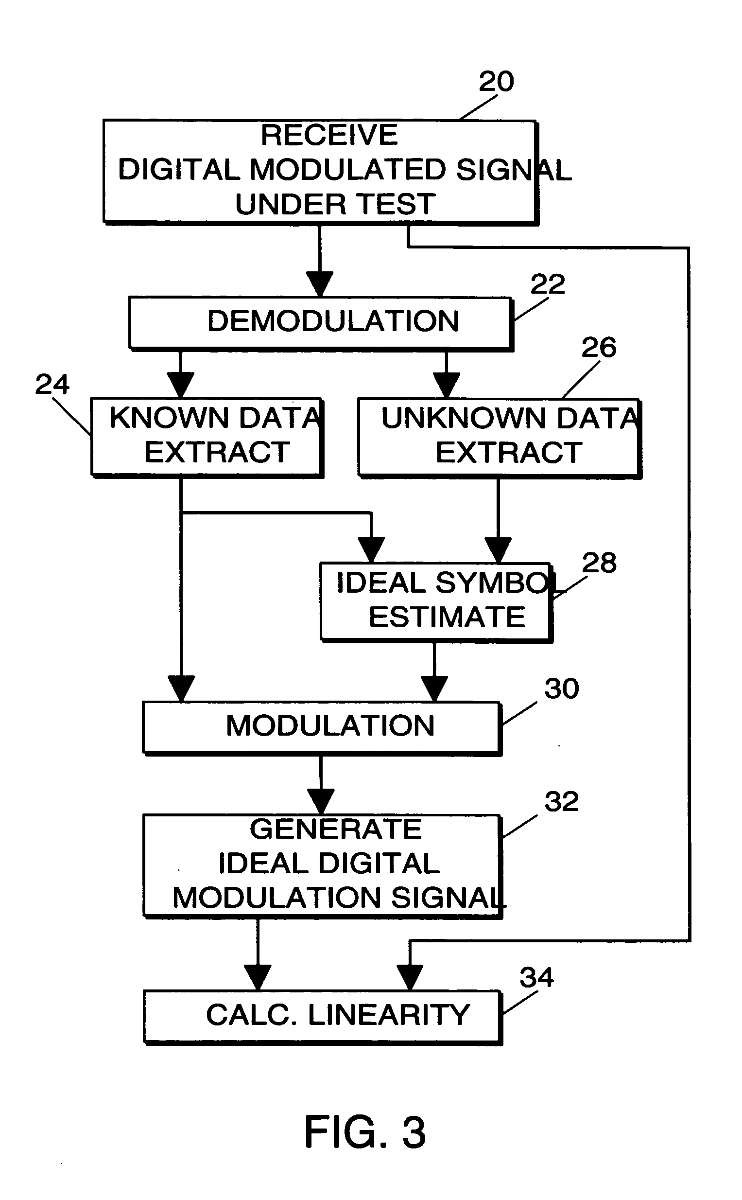
"The present invention provides a system for measuring the characteristics of a digital modulation signal transmission circuit. This system uses a simple and low-lost method. It receives a distorted digital modulation signal from the transmission circuit and demodulates it. It then separates the known data from the unknown data and estimates the ideal symbols for the unknown data using the known information. It calculates an ideal digital modulation signal using the ideal symbols and known information. The system also calculates the characteristic, such as amplitude linearity, between the distorted digital modulation signal and the ideal digital modulation signal. The calculated characteristic is displayed graphically. The system measures the characteristic of the transmission circuit even if it is in-service and requires only one input channel."

Problems solved by technology

Further, the conventional methods require that the transmission circuit stop its ordinary operation, making it difficult to measure a transmission system which is required to operate continuously and thus has few opportunities for stopping its operation, i.e., the measurement is an out-of-service measurement.
These methods provide accurate measurement of the characteristics of the transmission circuit, but the accuracy and cost are too much for just confirming whether or not there is a fatal error.
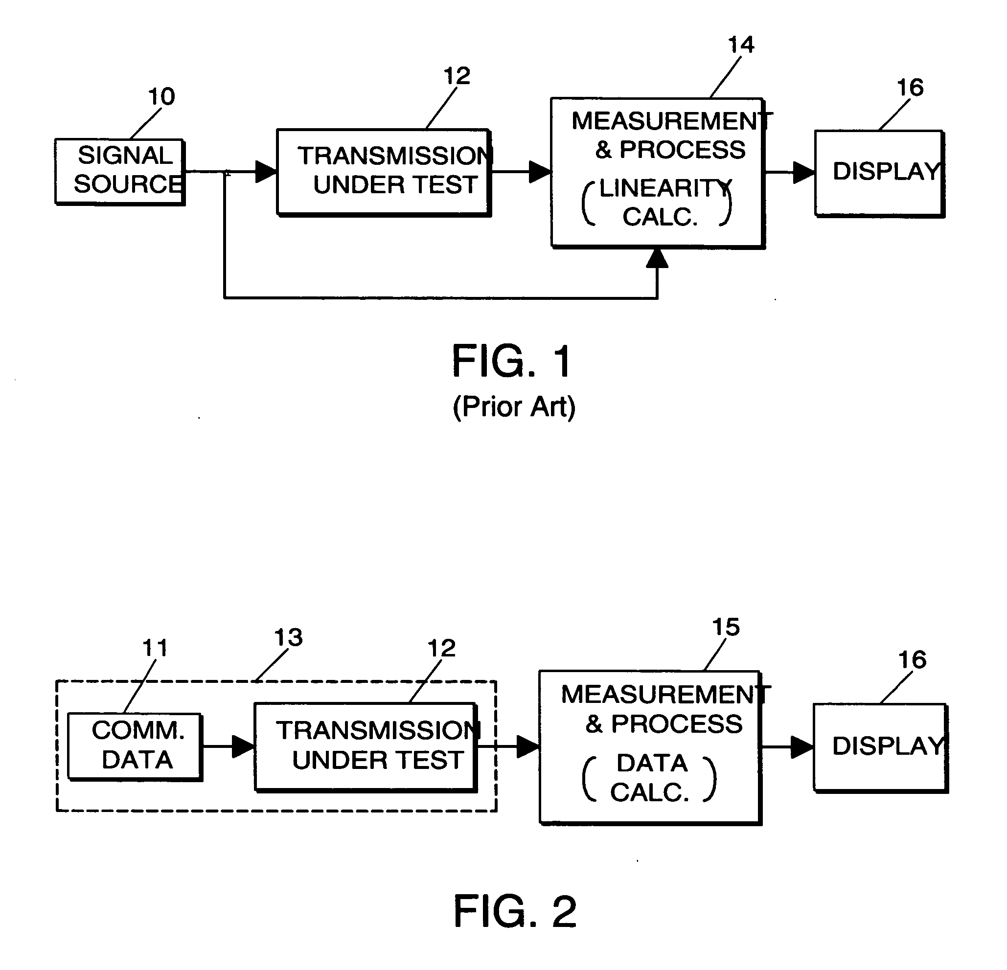
U.S. Pat. No. 6,275,523 discloses a system for in-service nonlinearity measurements of the transmission circuit by comparing transmitted signal samples from the output of the transmission circuit with reference signal samples regenerated from estimated transmitted symbols derived from the transmitted signal samples, but the system is complex and costly.

Method used


Image

  • Characteristic measurement system for a digital modulation signal transmission circuit
  • Characteristic measurement system for a digital modulation signal transmission circuit
  • Characteristic measurement system for a digital modulation signal transmission circuit

Examples


Embodiment Construction

[0015] Referring now to FIG. 2, a transmission circuit 12 receives an input digital modulation signal from a communication data source 11 and provides a distorted digital modulation signal. A measurement and processing circuit 15 receives the distorted digital modulation signal from the transmission circuit 12 to determine its characteristics. The results from the measurement and processing circuit 15 are provided to a display 16.

[0016]FIG. 3 shows a flowchart of a characteristic measurement process performed by the measurement and processing circuit 15. For this example the characteristic being measured is transmission circuit linearity. The measurement and processing circuit 15 may be a combination of a communication measurement instrument, such as a spectrum analyzer, etc., and a personal computer (PC). The measurement and processing circuit 15 conducts the measurement process according to a program previously stored in a built-in storage device, such as a hard disk drive (not s...


PUM


Abstract

Measurement of a characteristic of a digital modulation signal transmission circuit is calculated using only a distorted digital modulation signal from the transmission circuit. A measurement and processing circuit receives and demodulates the distorted digital modulation signal from the transmission circuit, separates known and unknown data from the demodulated signal, and estimates ideal symbols for the unknown data using known information derived from the known data, such as modulation format information and pilot signals. Then the measurement and processing circuit calculates the characteristic, such as transmission circuit linearity, between the distorted digital modulation signal and a calculated ideal digital modulation signal based on the ideal symbols and known information. The characteristic measurement is displayed graphically.

Description

BACKGROUND OF THE INVENTION [0001] The present invention relates to characteristic measurement of a digital modulation signal transmission circuit, and more particularly to simple characteristic measurement system for a digital modulation signal transmission circuit which uses a single input channel for in-service measurements. [0002] Mobile phone systems, terrestrial digital broadcasting systems, wireless LANs, etc. use digital modulation communication systems. For example, for wireless LAN a signal is first modulated by different symbol rates, such as QPSK (Quadrature Phase Shift Keying), 16QAM (Quadrature Amplitude Modulation), etc. according to transmission requirements, and then by OFDM (Orthogonal Frequency Division Multiplexing) to transmit the signal as a wireless signal. [0003] Digital modulation has tolerance for distortion. For example, a symbol of a QPSK modulated signal takes one of the four defined positions on an IQ plain and, even if the positions of actual symbols d...

Claims


Application Information

Patent Timeline
Patent Type & Authority Applications(United States)
IPC IPC(8): G01R29/06H04L27/00H04J11/00H04L1/20H04L1/24H04L12/26H04L27/04
CPCH04L1/206H04B17/18H04L1/242
Inventor AKITA, YONEO
Owner AKITA YONEO
Learn More