
Asymmetrical multiphase DC-to-DC power converter

a technology of dc-to-dc converter and multi-phase, which is applied in the direction of electric variable regulation, process and machine control, instruments, etc., can solve the problems of decreasing the efficiency of the converter as the inductor value decreases, and achieves 100% leakage current, high efficiency, and high efficiency.

Active Publication Date: 2005-05-05
INTERSIL INC
View PDF12 Cites 49 Cited by
  • Summary
  • Abstract
  • Description
  • Claims
  • Application Information

AI Technical Summary

Benefits of technology

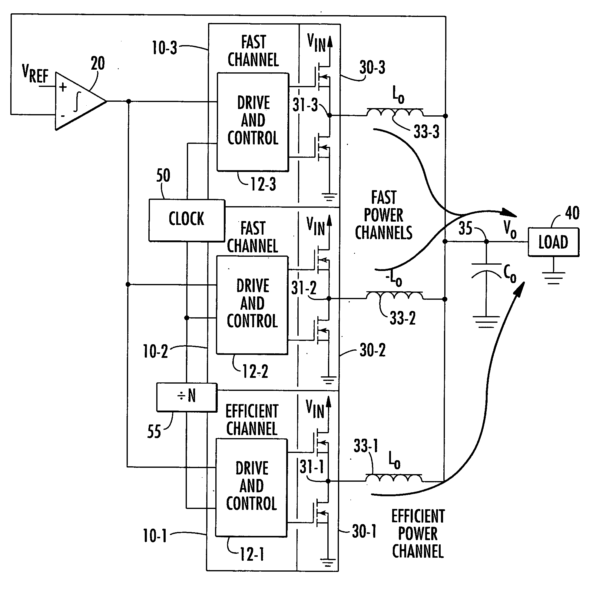
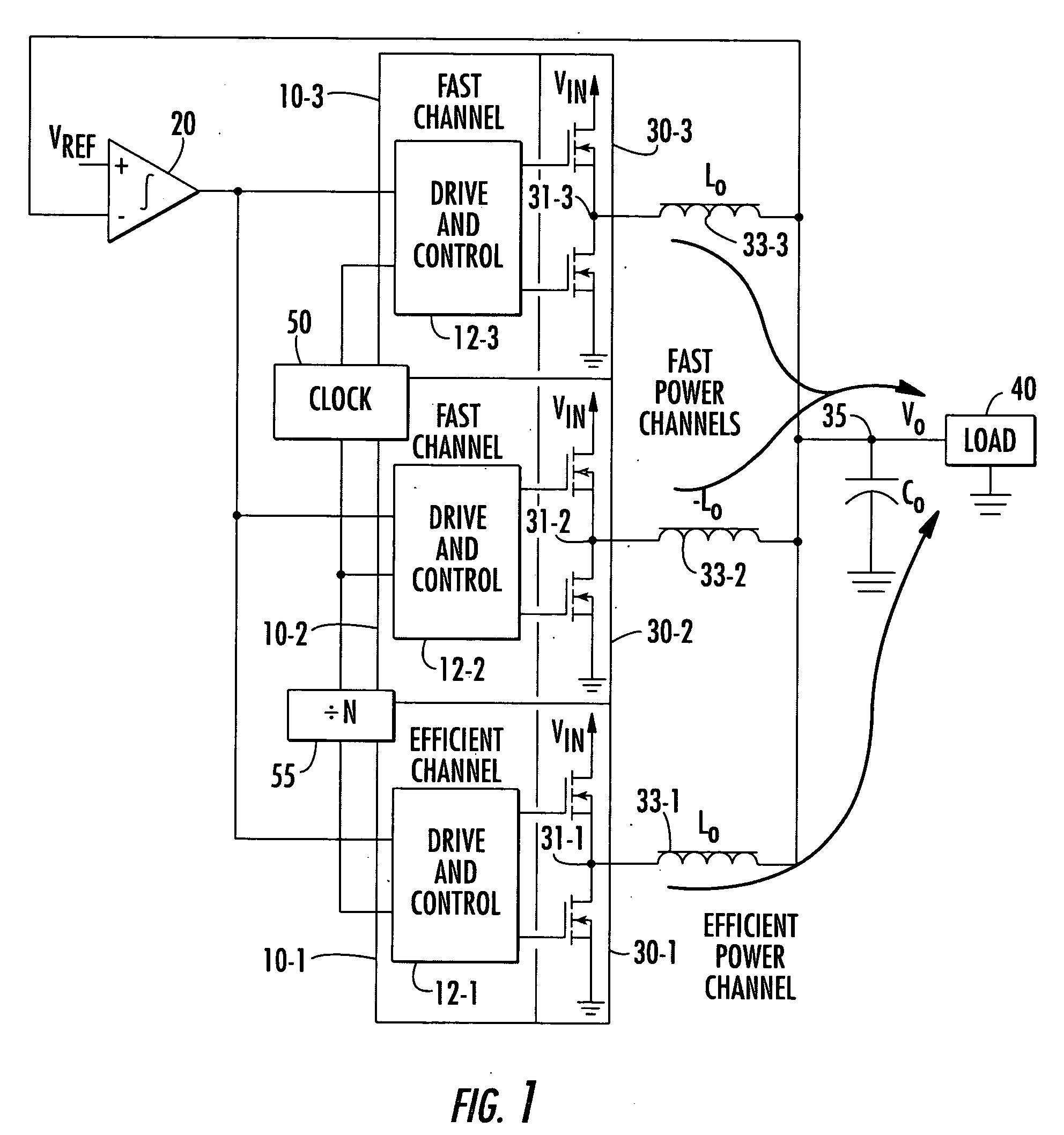
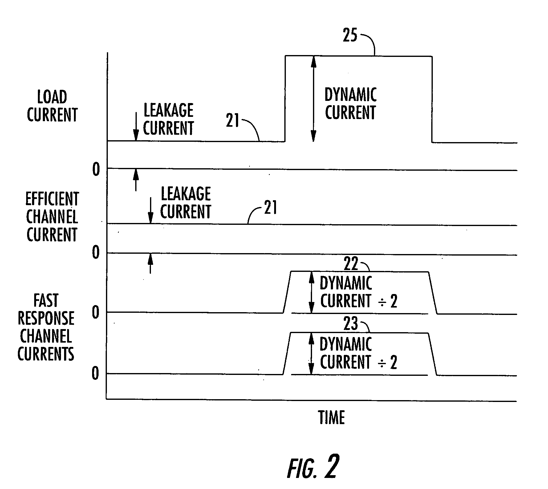
[0004] As will be described, the resulting asymmetrical multiphase DC-DC converter in accordance with the present invention may be configured to emphasize (utilize) the high efficiency channel for light load conditions (e.g., up to on the order of 12-15 amps), wherein the high efficiency channel is used to provide 100% of leakage current. This allows the converter to offer longer battery life in notebook power supply applications, and reduced thermal loading (heat) in desktop computer applications, that spend a large portion of their operating time in leakage current mode. With the high efficiency channel being used to supply 100% of the leakage current, the remaining fast response time-based channels are employed to handle high load current conditions. In a two fast response time channel embodiment, each of these fast channels is controlled so as to handle half of the high load current demand.

Problems solved by technology

On the other hand, the efficiency of the converter decreases as the inductor value decreases, due to an increase in RMS current and switching losses.

Method used


Image

  • Asymmetrical multiphase DC-to-DC power converter
  • Asymmetrical multiphase DC-to-DC power converter
  • Asymmetrical multiphase DC-to-DC power converter

Examples


Embodiment Construction

[0008] Before describing in detail the new and improved asymmetrical multiphase DC converter architecture of the present invention, it should be observed that the invention resides primarily in modular arrangements of conventional DC power supply circuits and components, and control circuitry therefor that controls the operations of such circuits and components. In a practical implementation these modular arrangements may be readily configured as field programmable gate array (FPGA)-implementation and application specific integrated circuit (ASIC) chip sets.

[0009] Consequently, the configuration of such arrangements of circuits and components and the manner in which they are interfaced with equipment powered thereby (such as a microprocessor) have, for the most part, been illustrated in the drawings by readily understandable block diagrams, and associated timing diagrams therefor, which show only those specific details that are pertinent to the present invention, so as not to obscu...


PUM


Abstract

A multiphase DC-DC converter architecture, in which respectively different channels have different operational performance parameters. These different parameters are selected so as to enable the converter to achieve an extended range of high efficiency. The converter contains a combination of one or more fast response time-based converter channels, and one or more highly efficient converter channels in respectively different phases thereof and combines the outputs of all the channels. The efficiency of the asymmetric multiphase converter is higher at light loads (up to approximately 12 amps), enabling it to offer longer battery life in applications that spend most of their operating time in the leakage mode, as noted above.

Description

FIELD OF THE INVENTION [0001] The present invention relates to DC power supply systems and subsystems thereof, and is particularly directed to a new and improved multiphase DC-DC converter architecture, in which respectively different channels thereof have different operational performance parameters, so as to enable the converter to achieve an extended range of high efficiency. BACKGROUND OF THE INVENTION [0002] Selecting the value of an inductor in a DC-DC converter involves a trade-off between the converter's response time and its efficiency. Employing a small inductor enables the converter to deliver current more rapidly than a converter having a large valued inductor. A small inductance value usually requires a relatively high switching frequency in order to help limit the peak-to-peak ripple current. On the other hand, the efficiency of the converter decreases as the inductor value decreases, due to an increase in RMS current and switching losses. SUMMARY OF THE INVENTION [000...

Claims


Application Information

Patent Timeline
IPC IPC(8): G05F1/40H02M3/02H02M3/158
CPCH02M3/1584Y02B70/10H02M1/0032
Inventor WALTERS, MICHAEL M.PETRICEK, SHEA L.
Owner INTERSIL INC
Learn More