Incubator

a technology of incubator and rotor, which is applied in the field of incubators, can solve the problems of increasing affecting the rigidity of the incubator rotor, and the inability to suppress the fluctuation of the distance, so as to and reduce the manufacturing cost of the incubator

Inactive Publication Date: 2005-04-28
FUJIFILM CORP
View PDF9 Cites 0 Cited by
  • Summary
  • Abstract
  • Description
  • Claims
  • Application Information

AI Technical Summary

Benefits of technology

[0015] In view of the foregoing observations and description, the primary object of the present invention is to provide an incubator which can accurately measure the optical density of the dry analysis element in all the element chambers of the incubator without using a sliding support and can be manufactured at low cost even if it is provided with a large number of element chambers and is large in size.
[0016] Another object of the present invention is to provide an incubator which is precise in rotation and small in weight and in which the dry analysis elements can be easily discarded after measurement.

Problems solved by technology

However, the approach disclosed in the aforesaid Japanese patent publication is disadvantageous in that though fluctuation of the distance can be held in an acceptable range where the influence of variation of the distance on the light measuring sensitivity can be suppressed by the arrangement of the optical components so long as the diameter of the incubator rotor is small and the rotational displacement of the incubator rotor is small, fluctuation of the distance becomes too large for the optical components to suppress the influence of variation of the distance on the light measuring sensitivity in an acceptable range when the number of the dry analysis elements to be accommodated in the incubator increases and the diameter of the incubator rotor increases.
An attempt to limit the rotational displacement of a large incubator rotor increases requirement on processing accuracy and fabricating accuracy of the components of the incubator rotor, thereby adding to the manufacturing cost of the incubator.
The approach disclosed in the United states patent is disadvantageous in that as the sliding support wears, the rotational displacement of the incubator rotor increases and the incubator rotor drive mechanism can become unstable due to nonuniform load and wear of the sliding support will produce dust.
However, as the number of the dry analysis elements to be accommodated in the incubator increases and the diameter of the incubator rotor increases, the diameter of the discarding hole must be large in order to discard the dry analysis elements in all the element chambers by a limited stroke of the element transfer member.
When the diameter of the discarding hole is enlarged and the diameter of the rotating shaft of the incubator rotor is increased, the diameter of the bearing member for supporting the rotating shaft must be large, which adds to the manufacturing cost of the bearing member.
Especially when the bearing member must support the rotating shaft of the incubator rotor so as to suppress the rotational displacement of the incubator rotor in the acceptable range as described above, the manufacturing cost of the bearing member is further increased.
On the other hand, when the diameter of the element discarding hole is reduced, the distance over which the dry analysis elements are conveyed to be discarded becomes longer, which adds to the length and stroke of the element transfer member and increases the overall size and weight of the apparatus.

Method used


Image

  • Incubator
  • Incubator
  • Incubator

Examples


Embodiment Construction

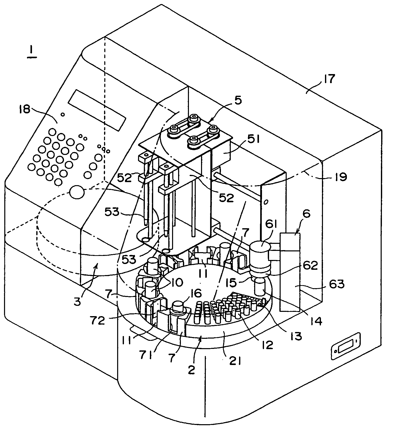
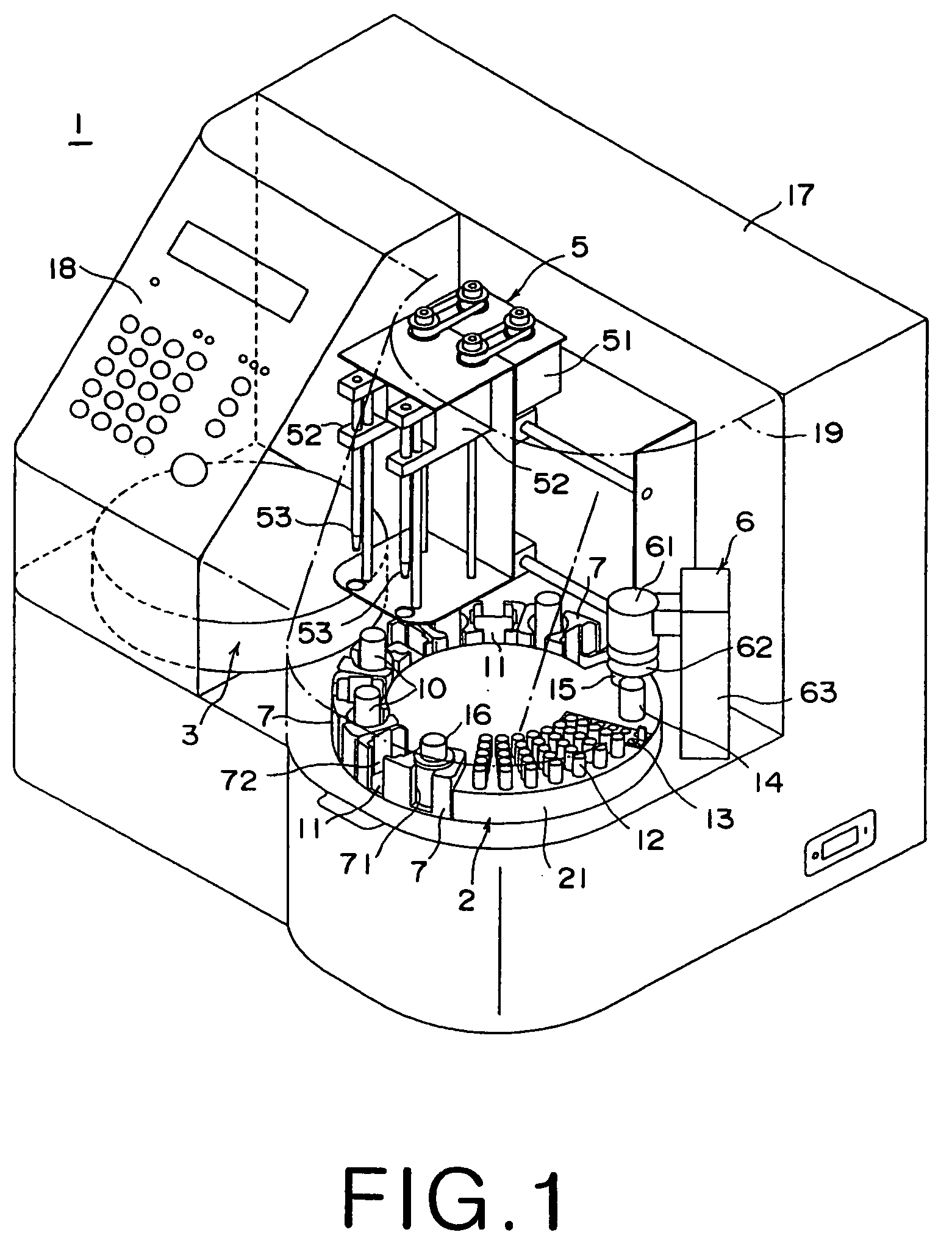
[0035] In FIG. 1, a biochemical analysis system 1 comprises a system body 17 and a circular sample tray 2 is provided on one side of the front portion of the system body 17. A circular incubator 3 is provided on the other side of the front portion of the system body 17, and a spotting station (not shown) is provided between the sample tray 2 and the incubator 3. Further a spotting nozzle unit 5 is provided on an upper portion of the system body 17 to be movable right and left. A dry analysis element 11 held in a sample cartridge 7 is moved to the spotting station and spotted with a sample. Then the dry analysis element 11 spotted with the sample is transferred to the incubator 3. A blood filtering unit 6 for separating blood plasma from blood is provided beside the sample tray 2.

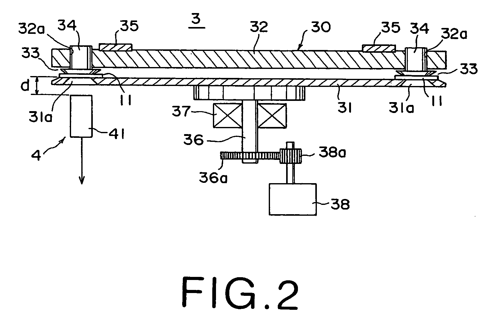
[0036] The incubator 3 comprises an incubator rotor 30 and a measuring means 4. The incubator rotor 30 comprises lower and upper disc members 31 and 32, and a plurality of element chambers 33 in which the d...


PUM

PropertyMeasurementUnit
angleaaaaaaaaaa
concentrationaaaaaaaaaa
temperatureaaaaaaaaaa

Abstract

An incubator includes a rotating incubator rotor. The incubator rotor is provided with a plurality of element chambers which are arranged along the outer periphery of the incubator rotor and each of which accommodates a dry analysis element spotted with a sample and incubates the dry analysis element. A light measuring system has a light measuring head which measures the optical density of the dry analysis element. The light measuring system is provided with a correction system which compensates for fluctuation in the value of the optical density of the dry analysis element in each of the element chambers as measured by the light measuring head generated due to fluctuation in the distance between the light measuring head and the element chamber on the basis of a correction value which has been stored in the correction system element chamber by element chamber.

Description

BACKGROUND OF THE INVENTION [0001] 1. Field of the Invention [0002] This invention relates to an incubator which is used in a biochemical analysis system, in which a sample such as blood or urine is spotted onto a dry analysis element and, for instance, the concentration of a specific biochemical component contained in the sample is detected, to keep the dry analysis element at a constant temperature in order to measure change of the optical density. [0003] 2. Description of the Related Art [0004] Recently, there has been put into practice a colorimetric dry (dry-to-the touch) analysis element with which the content of a specific biochemical component or a specific solid component contained in a sample liquid can be quantitatively analyzed by simply spotting a droplet of the sample liquid. Since being capable of analyzing samples easily and quickly, the biochemical analysis systems using such dry analysis elements are suitably used in medical institutions, laboratories and the like....

Claims


Application Information

Patent Timeline
Patent Type & Authority Applications(United States)
IPC IPC(8): G01N1/38G01N21/25G01N35/00G01N35/02G01N35/10
CPCG01N1/38Y10T436/111666G01N35/025G01N2035/00079G01N2035/00089G01N2035/00108G01N2035/00376G01N2035/00752G01N2035/103G01N2035/1032G01N2035/1034G01N2035/1053G01N2035/106Y10T436/11G01N21/253
Inventor SUGAYA, FUMIOKOMATSU, AKIHIRO
Owner FUJIFILM CORP
Why Eureka
Try Eureka