
Hybrid vehicle

a hybrid vehicle technology, applied in the direction of electric propulsion mounting, cycle equipment, electric propulsion, etc., can solve the problems of difficult to achieve size reduction, achieve the effect of improving layout efficiency, suppressing power consumption, and improving layout efficiency

Inactive Publication Date: 2005-04-28
HONDA MOTOR CO LTD
View PDF7 Cites 11 Cited by
  • Summary
  • Abstract
  • Description
  • Claims
  • Application Information

AI Technical Summary

Benefits of technology

[0007] With this type of structure, because power transmission from the drive shaft side to the power transmission is normally disengaged at the time of shifting to a regeneration operation from the drive wheel to the motor, the disengage operation is not necessary. Since power transmitted at the time of regeneration operation from the drive wheel to the motor is not consumed by the power transmission means, it is possible to improve charging efficiency at the time of regeneration. Also, at the time of switching from a state where the drive source is only the engine to a state where the drive source is only the motor, since it is no longer necessary to have a drive source switching operation, power transmitted from the motor to the drive wheel is not consumed by drive of the power transmission means and it is possible to improve energy transmission efficiency. If a one-way clutch is used as unidirectional power transmission means, it is possible to reduce the overall size of the power unit compared to the case of using a centrifugal clutch.
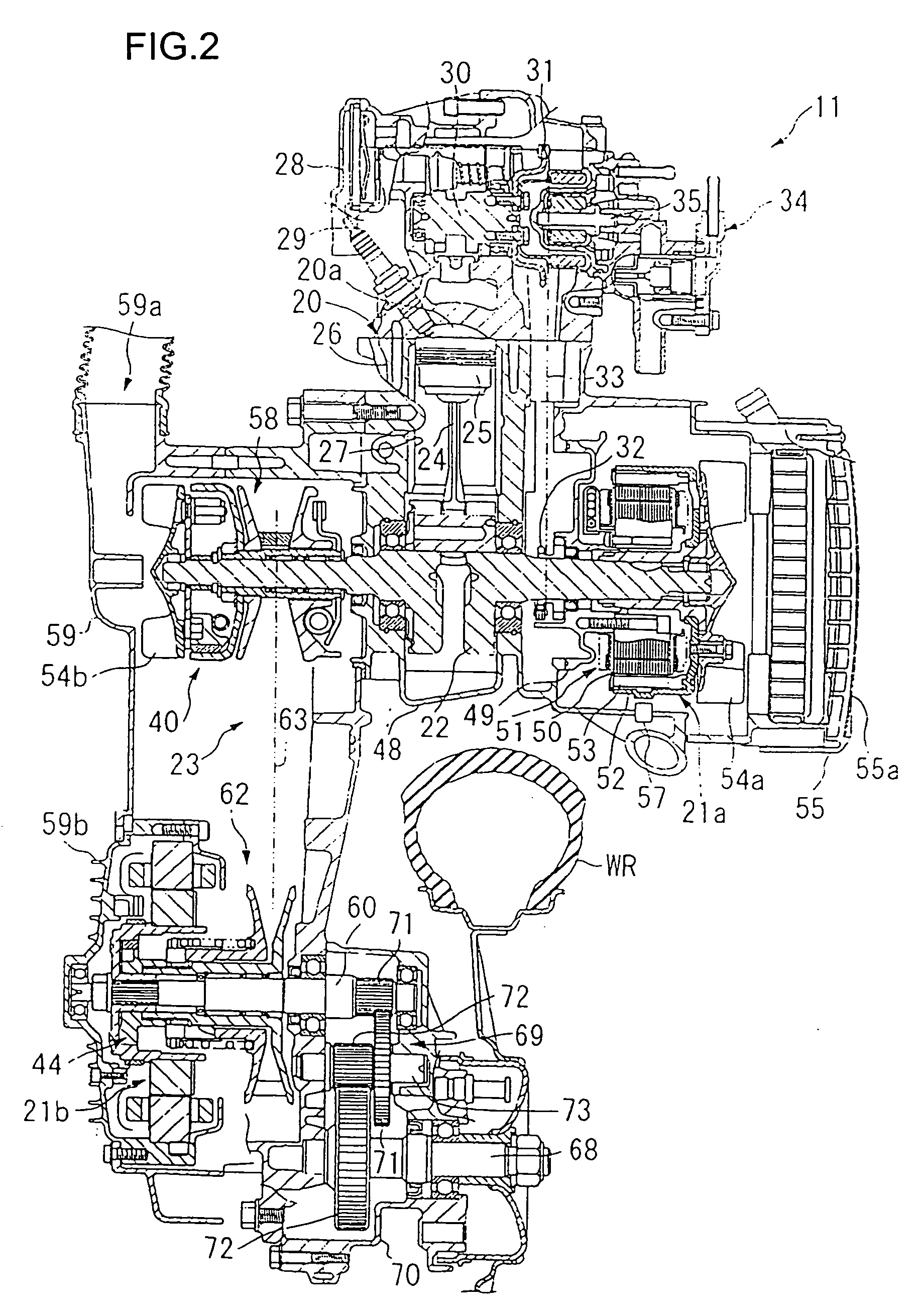
[0009] The power transmission means is constructed with a belt converter for transmitting power from the engine to the drive shaft using an endless belt and the belt converter is provided with resilient means for urging a driven side movable pulley in a widthwise direction of the vehicle, and the unidirectional power transmission means is arranged adjacent to the resilient means. With this type of structure, it is possible to make effective use of dead space that is likely to occur next to the resilient means and to further improve layout efficiency.
[0010] A power unit for the hybrid vehicle including a power source has a pivot section supported in a swingable manner at the center, and the motor is arranged adjacent to a driven side pulley of the power transmission means. With this type of structure, since the distance between the motor and the transmission means is made as short as possible, it is possible to suppress power consumption between the two to the utmost and to further improve layout efficiency.

Problems solved by technology

If the motor and the centrifugal clutch are both large, it is difficult to achieve reduction in size even if they are housed in the transmission case.

Method used


Image

  • Hybrid vehicle
  • Hybrid vehicle
  • Hybrid vehicle

Examples


Embodiment Construction

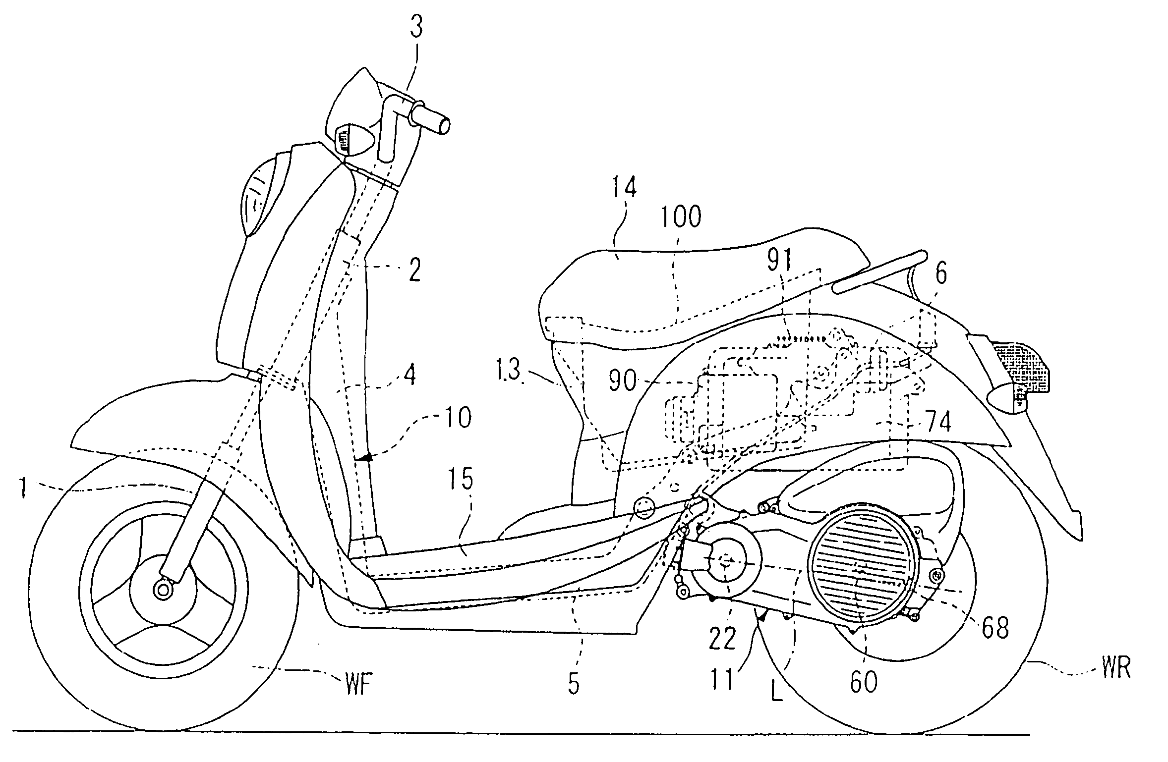
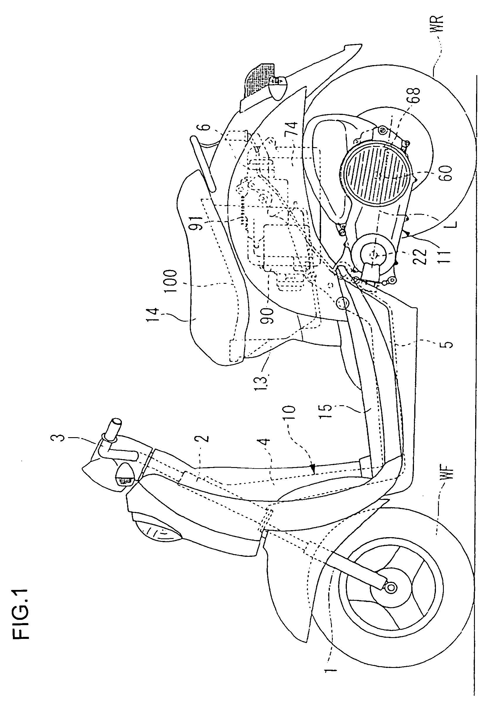
[0017] An embodiment of a hybrid vehicle of the present invention will now be described in the following with reference to the drawings of FIG. 1 to FIG. 4. In the following description, front side refers to the advancing direction of the vehicle, and right side and left side refer to the right side and the left side facing in the advancing direction of the vehicle.

[0018] As shown in FIG. 1, a hybrid vehicle of this embodiment is unit swing type two-wheeled vehicle, having a front fork 1 where a front wheel WF is axially supported at the front of the vehicle. This front fork 1 is pivoted on a head pipe 2, and can be steered by operating a handle 3. A downpipe 4 running to the rear and down is attached from the head pipe 2, and a middle frame 5 extends substantially horizontally from a lower end of this down pipe 4. Also, a rear frame 6 is formed running rearwards and upwards from a rear end of the middle frame 5. One end of a power unit 11, as a drive power source, is pivoted to th...


PUM


Abstract

In order to do away with the need for a power source switching operation, and to improve motor regeneration charge efficiency in a hybrid vehicle, a one-way clutch is provided between an internal combustion engine and an electric drive motor.

Description

FIELD OF THE INVENTION [0001] This invention relates to a hybrid vehicle having an internal combustion engine and an electric motor as power sources. BACKGROUND OF THE INVENTION [0002] Japanese patent laid-open No. Hei. 8-175473 discloses a hybrid vehicle that can switch between travel using an electric motor only and travel using an internal combustion engine only depending on travel conditions of the vehicle for the purpose of achieving lowered fuel consumption and lowered exhaust gas pollution. The hybrid vehicle has power from an internal combustion engine transmitted to a drive wheel by means of a V-belt type power transmission unit and a centrifugal clutch, and an electric motor is also connected to this drive shaft via a switching mechanism for carrying out switching of power of the V-belt transmission unit. [0003] With the structure described above, since the centrifugal clutch is arranged between the drive shaft and the V-belt transmission unit, in the cases such as where a...

Claims


Application Information

Patent Timeline
Patent Type & Authority Applications(United States)
IPC IPC(8): B60K6/36B60K6/383B60K6/40B60K6/442B60K6/543B60K17/04B60L50/16B62J99/00B62M7/12B62M9/04B62M23/02
CPCB60K6/383B60K6/40B60K6/48B60K6/543Y02T10/70B60L2200/12B60Y2200/12Y02T10/6221Y02T10/7077B60L11/14B60L50/16Y02T10/62Y02T10/7072B60K6/22B62M23/02
Inventor TSUKADA, YOSHIAKIKUROKI, MASAHIROOZEKI, TAKASHITSUTSUMIZAKI, TAKASHI
Owner HONDA MOTOR CO LTD
Learn More