
Mass flow meter with chip-type sensors

a technology of mass flow meter and chip-type sensor, which is applied in the direction of volume/mass flow measurement, measurement device, instrument, etc., can solve the problems of inaccuracy of flow measurement, reduced resistance, and more current flowing through, so as to achieve more accurate temperature sensing

Inactive Publication Date: 2005-04-28
HEETRONIX
View PDF11 Cites 4 Cited by
  • Summary
  • Abstract
  • Description
  • Claims
  • Application Information

AI Technical Summary

Benefits of technology

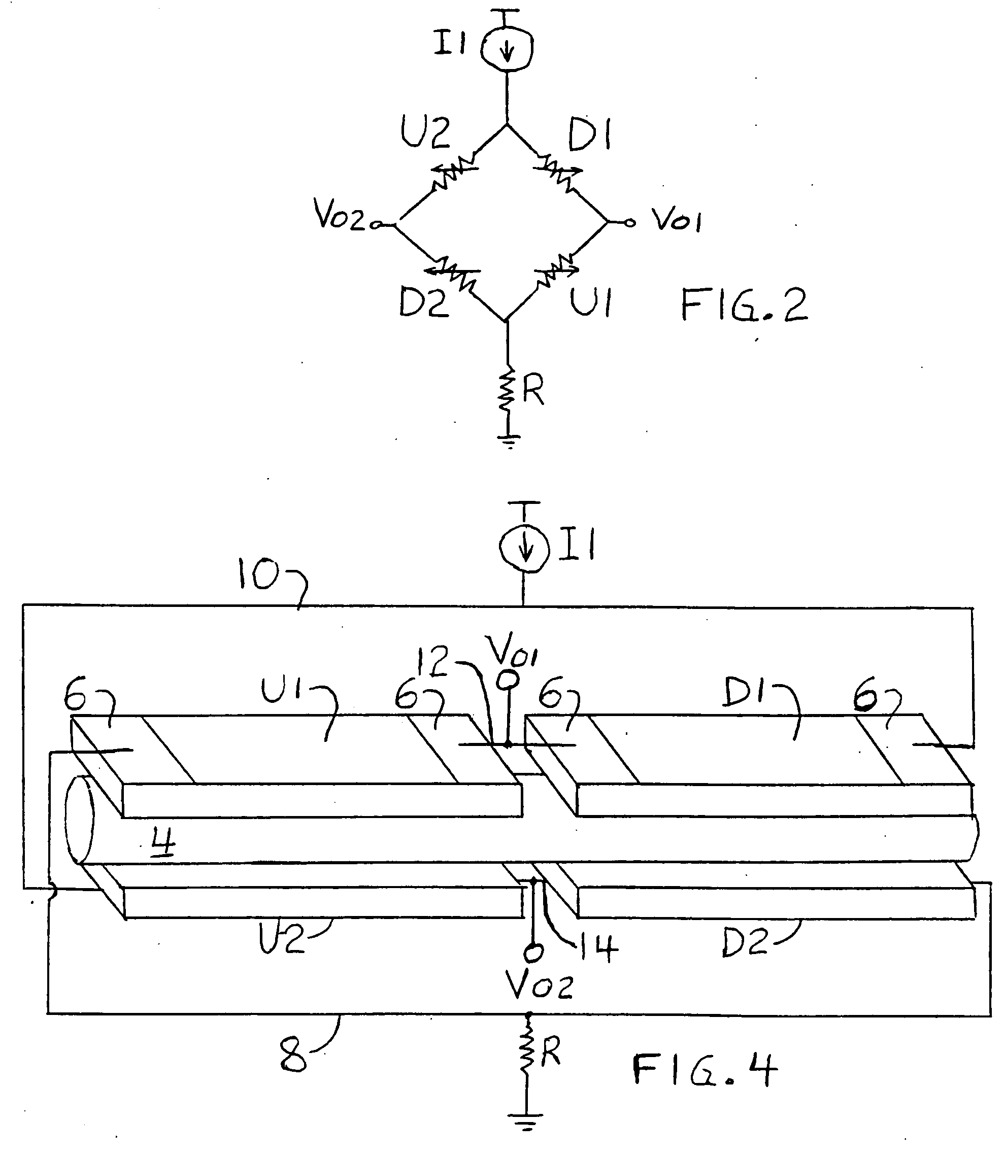
"The present invention relates to a system for measuring the temperature of a fluid flowing through a conduit, which involves using at least four mutually spaced temperature sensors placed symmetrically with respect to the conduit. These sensors can be discrete chip-type elements that are connected in a four-sensor bridge circuit to provide an indication of the fluid's mass flow rate. The sensors can be placed at various locations along the fluid flow path, such as on the conduit's outer surface, inner conduit surface, openings in the conduit wall, or projecting into the interior of the conduit. The symmetrical placement of the sensors enables more accurate temperature sensing and is useful for both four-sensor bridge circuits and other MFM configurations employing one or more sensor pairs. The described MFM can be used to govern the fluid flow through the conduit by applying its output to a flow control valve for the conduit."

Problems solved by technology

A principal problem with volumetric flow meters relates to the measurement of gas flow rate.
Changes in the pressure or temperature of the gas can cause inaccuracies in the flow measurements.
A fluid flowing through the tube causes a reduction in the temperature of the upstream sensor, which reduces its resistance (for a positive temperature coefficient sensor), causing more current to flow through it.
While they are in widespread use, presently available MFCs suffer from one or more of the following characteristics: relatively high temperature sensor drift, low sensitivity, long response times, waste associated with the difficulty of handling ultra-fine platinum wire during manufacture, additional electronics required to quantify the electrical responses of low sensitivity temperature sensors, and errors resulting from the circuitry for low sensitivity temperature sensors, when used in conjunction with high sensitivity sensors.

Method used


Image

  • Mass flow meter with chip-type sensors
  • Mass flow meter with chip-type sensors
  • Mass flow meter with chip-type sensors

Examples


Embodiment Construction

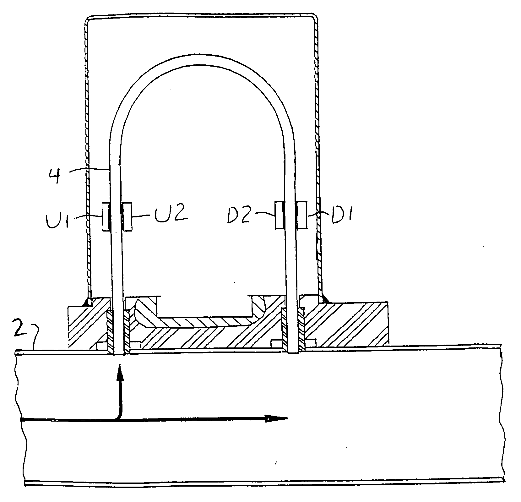
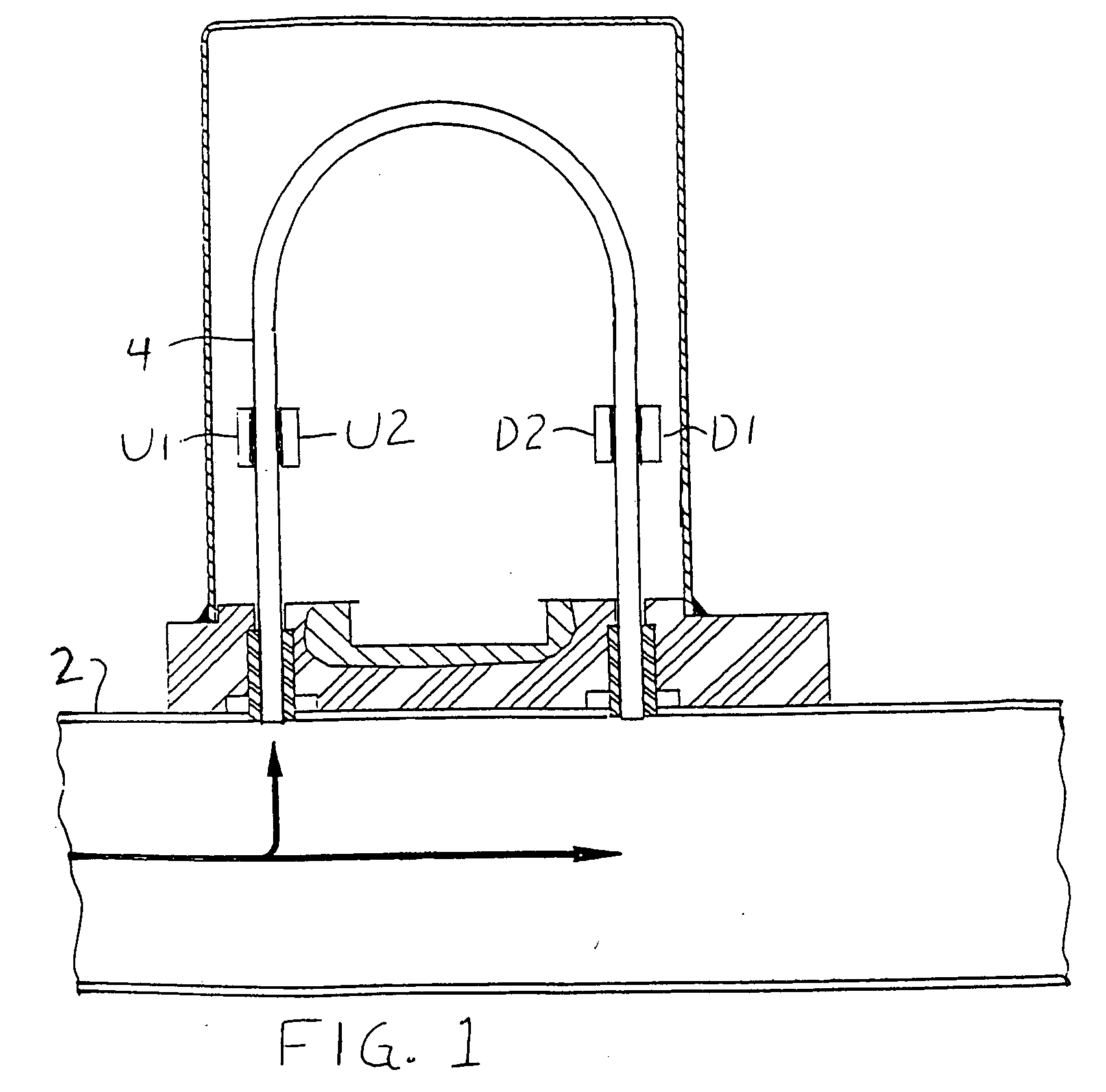
[0034] A capillary tube MFM in accordance with one embodiment of the invention is illustrated in FIG. 1. A minor portion of a fluid flow, either gas or liquid, through a main conduit 2 is diverted to a capillary tube 4; the main conduit and capillary tube structure can be conventional. The cross-sections of the main conduit and capillary tube are precisely machined in a conventional manner to assure their fluid flow rates are equal. However, instead of the platinum wire windings previously provided around the capillary tube, a pair of chip-type temperature sensors U1 and U2 are provided at an upstream location along the tube, and another pair of chip-type sensors D1 and D2 at a downstream location along the tube. The sensors of each pair are preferably positioned symmetrically at 180° intervals, on opposite sides of the tube. This allows for a more accurate sensing of the fluid temperature within the tube, in case the fluid temperature varies slightly from one side of the tube to th...


PUM


Abstract

A mass flow meter employs discrete chip-type temperature sensors to sense a fluid flow rate. The sensor can be a semiconductor chip such as SiC or silicon, or thin film tungsten on an AlN substrate. The sensors can be distributed symmetrically with respect to the conduit through which the fluid flows, and can be connected in a four-sensor bridge circuit for accurate flow rate monitoring. An output from the mass flow meter can be used to control the fluid flow.

Description

RELATED APPLICATION [0001] This application claims the benefit of provisional application Ser. No. 60 / 392,380, filed Jun. 28, 2002.BACKGROUND OF THE INVENTION [0002] 1. Field of the Invention [0003] This invention relates to mass flow meters, and more particularly to chip-type temperature sensors and four-sensor bridge circuits for mass flow meters. [0004] 2. Description of the Related Art [0005] Numerous different methods are employed to measure the flow rate of gases and liquids. They can generally be divided into two categories: those that measure volumetric flow, and those that measure mass flow. [0006] An example of a volumetric flow meter is a tapered tube through which the gas or liquid travels, displacing a float in the tube. When there is no flow, the float rests at the bottom of the tube, sealing its narrower end. As the fluid flows through the tube, the float rises proportionally to the volumetric fluid flow. [0007] A principal problem with volumetric flow meters relates ...

Claims


Application Information

Patent Timeline
Patent Type & Authority Applications(United States)
IPC IPC(8): G01F1/00G01F1/684G01F1/692G01F1/696
CPCG01F1/6845G01F5/00G01F1/6847G01F1/692
Inventor VINCZE, CRAIG A.GIBSON, JAMESPARSONS, JAMES D.FEHLMAN, THOMAS E.
Owner HEETRONIX
Learn More