Hydrodynamic bearing system

a bearing system and hydrodynamic technology, applied in the direction of sliding contact bearings, bearing unit rigid support, instruments, etc., can solve the problems of reducing the load carrying capacity of axial bearings, affecting the bearing performance, and disrupting the force balance, etc., to achieve the effect of effective lubricant circulation

Inactive Publication Date: 2005-04-21
MINEBEA CO LTD
View PDF5 Cites 25 Cited by
  • Summary
  • Abstract
  • Description
  • Claims
  • Application Information

AI Technical Summary

Benefits of technology

[0009] It is thus the object of the invention to provide a hydrodynamic bearing system in which the above-mentioned problems when connecting the parts can be avoided, and a more effective circulation of lubricant can be achieved.
[0014] Here, either the outer circumference of the shaft in the area of connection with the thrust plate can be knurled or the inner circumference of the thrust plate. It is particularly advantageous if the shaft is knurled since the shaft and knurl can be formed to size together in one operation, by grinding for example. A pressfit connection with a previously knurled and ground connecting surface has the advantage over parts with smooth, non-interrupted cylindrical fit surfaces that pressfitting can be carried out using less force and there is a greatly reduced tendency for the parts to “seize” and tilt.
[0015] Knurling is carried out before final grinding or lapping of the parts that are to be connected. Knurling is a common process in metal working and can be carried out relatively simply and at low cost.
[0016] In a preferred embodiment of the invention, the knurling extends over the entire joint length between the shaft and the thrust plate. In this case, axial “channels” remain in the fit joint after the parts have been joined and are distributed evenly over its circumference, the “channels” creating a fluid-carrying connection between the bearing gaps of the axial bearing region abutting the two end faces of the thrust plate. Lubricant can move from one bearing gap to the other via these channels on the circumference of the shaft and flow back via the abaxial radial gap at the outer circumference of the thrust plate which goes to ensure a continuous circulation around the thrust plate. At the same time, this allows the thrust plate to float up more rapidly so that the critical area of mixed friction on start-up and run-down of the motor is passed through more rapidly.
[0017] This means that not only can the bearing fluid enter into and circulate in the axial bearing region from the radial bearing region via the bearing gap but also via these channels which are in direct axial extension of the radial bearing gap. The constant flow of fluid within the bearing gap goes to prevent local overheating of the bearing fluid and ensures a more even temperature distribution. This greatly lessens the probability of the bearing being damaged through stationary and rotating axial bearing components touching each other. Moreover, the bearing can be subjected to the same load in both axial directions although the stiffness characteristics can deviate from each other.

Problems solved by technology

This balance of forces, however, is disrupted by an additional force acting on the system which is created by the free end of the shaft also being subjected to fluid pressure in the bearing gap between the thrust plate and the cover plate.
Depending on the design and the load on the bearing, this imbalance of hydrodynamic pressure caused by the different active surfaces in the axial bearing can result in the bearing gap between the end face of the thrust plate and the bearing sleeve becoming so small that the frictional losses increasing disproportionately to the decrease in the bearing gap can cause a rise in the local temperature of the lubricant.
The load carrying capacity of the axial bearing, however, is reduced due to the thermally-induced decline in its viscosity as a result of which the already narrow bearing gap is reduced even further.
The end face of the thrust plate could then come dangerously close to the bearing sleeve and perhaps even touch it, which could go to shorten the useful life of the bearing or even result in damage to the bearing.
If the holes are not disposed in an exactly symmetric manner this could lead to an imbalance of the rotating parts.
In assembling such a bearing, in particular, when mounting the thrust plate onto the shaft and mounting the bearing sleeve into a bearing receiving portion, “seizing” of the pressfit surfaces can occur during the joining process due to the necessarily tight fit.
This can impair the concentricity and the evenness as well as the right angularity of the parts that are to be joined.

Method used


Image

  • Hydrodynamic bearing system
  • Hydrodynamic bearing system
  • Hydrodynamic bearing system

Examples


Embodiment Construction

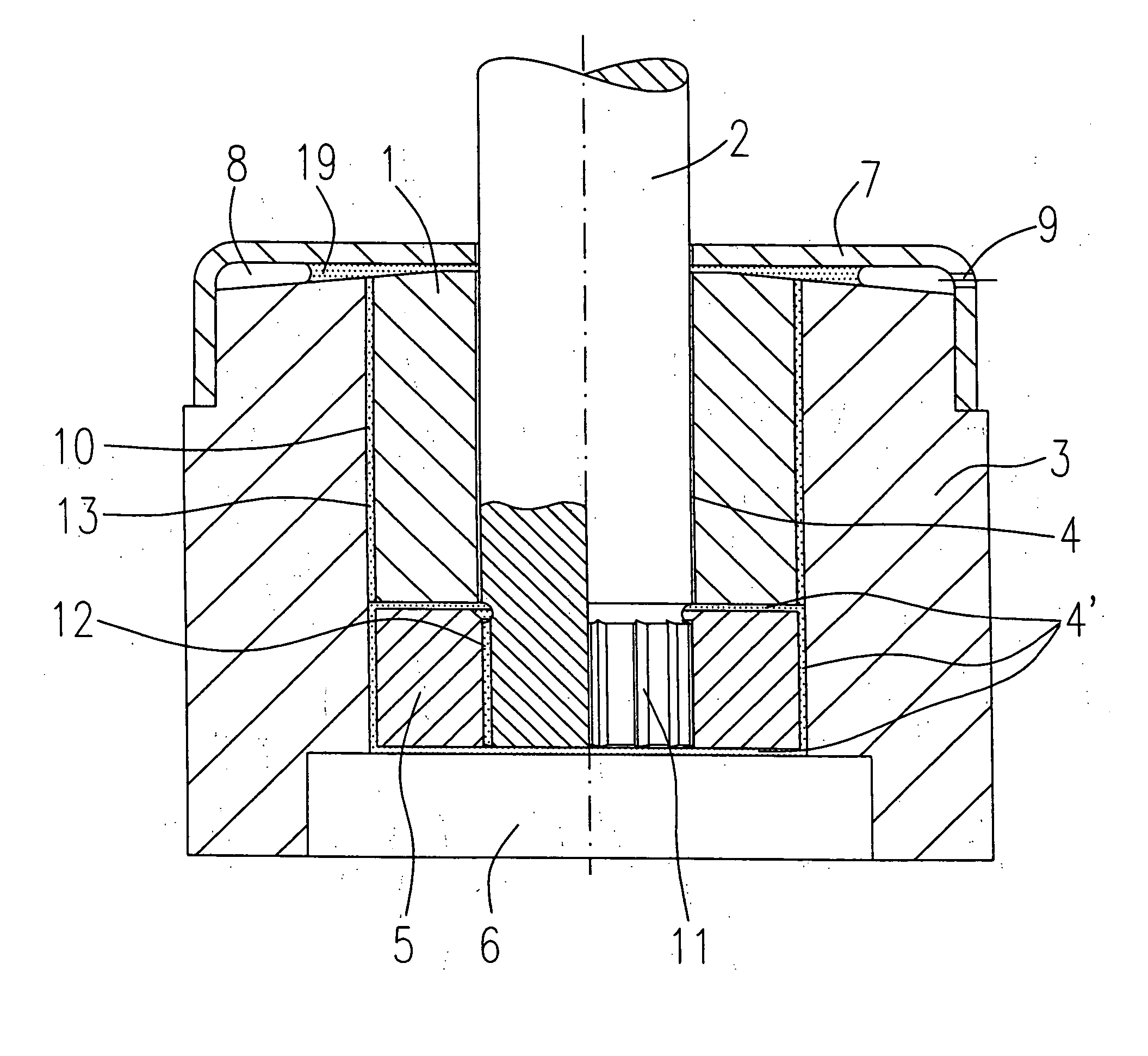
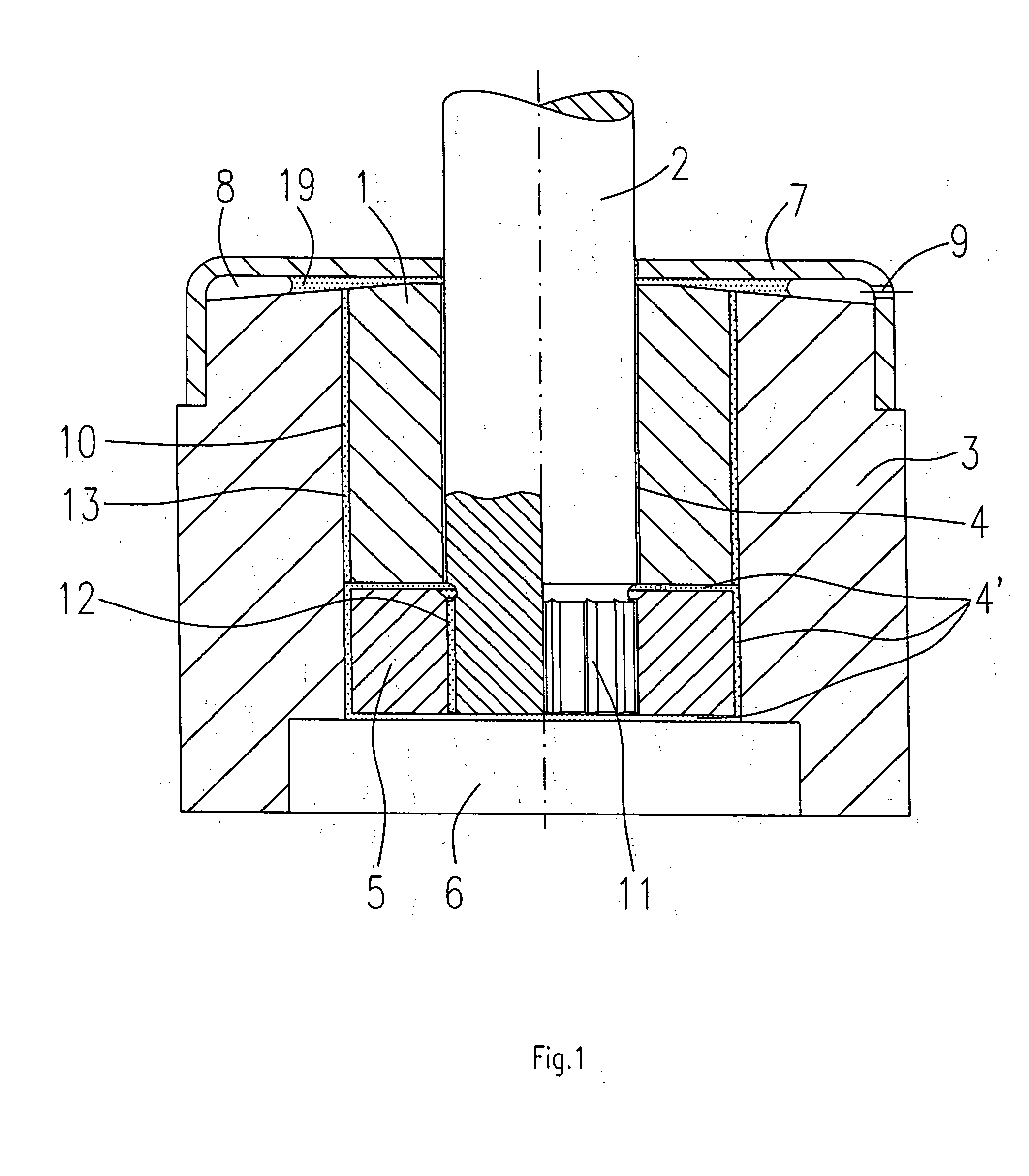
[0029] The drawings show hydrodynamic bearing systems for spindle motors in hard disk drives according to the invention. In the illustrated embodiments, the shaft is rotatably supported in a stationary bearing sleeve. It is of course clear that the invention also includes designs in which a stationary shaft is enclosed by a rotating bearing sleeve.

[0030] The bearing arrangement according to FIG. 1 comprises an inner bearing sleeve 1 having an axial cylindrical bore in which a shaft 2 is rotatably accommodated. The bearing sleeve 1 itself is pressed into a bearing receiving portion 3. Between the inside diameter of the bearing sleeve 1 and the slightly smaller outside diameter of the shaft 2, there is at least one radial bearing region provided with a bearing gap 4 that is filled with a lubricant, preferably a liquid bearing fluid. This radial bearing region is marked by a groove pattern (not illustrated) that is provided on the surface of the shaft 2 and / or on the inner surface of ...


PUM


Abstract

The invention relates to a hydrodynamic bearing system particularly for use as a rotary bearing in a spindle motor for a hard disk drive, comprising a shaft, a thrust plate firmly connected to the shaft by means of a pressfit connection and a bearing sleeve closed at least at one end by a cover plate, the bearing sleeve enclosing the shaft and the thrust plate with a slight radial or axial spacing forming a concentric bearing gap filled with a lubricant. In the hydrodynamic bearing system according to the invention, it is provided that the outer circumference of the shaft, in the area of connection with the thrust plate, has a surface interrupted by regular depressions, preferably formed by knurling, in order to decrease the contact surface proportion of the fit surface. As an alternative, the inner circumference of the thrust plate can also be knurled in the area of connection with the shaft.

Description

BACKGROUND OF THE INVENTION [0001] The invention relates to a hydrodynamic bearing system particularly for spindle motors in hard disk drives according to the preamble of claim 1. Outline of the Prior Art [0002] Hydrodynamic bearings are being increasingly employed as rotary bearings in spindle motors, as used for example to drive platters in hard disk drives, alongside roller bearings which have been used for this purpose for a long time. A hydrodynamic bearing is a further development of a sliding bearing formed from a bearing sleeve having a cylindrical inner bearing surface and a shaft having a cylindrical outer bearing surface set into the sleeve. The diameter of the shaft is slightly smaller than the inside diameter of the sleeve as a result of which a concentric bearing gap is formed between the two bearing surfaces, the bearing gap being filled with a lubricant, preferably an oil, forming a continuous capillary film. [0003] Together, the bearing sleeve and shaft form the rad...

Claims


Application Information

Patent Timeline
IPC IPC(8): F16C17/02F16C17/04F16C17/10F16C33/10F16C33/74F16C35/02G11B19/20H02K5/16H02K7/08
CPCF16C17/026F16C17/10F16C33/103F16C2370/12F16C33/74G11B19/2018F16C33/107
Inventor OELSCH, JUERGEN
Owner MINEBEA CO LTD
Why Eureka
Try Eureka