Method and apparatus for charging batteries in a system of batteries
a battery and battery system technology, applied in the field of battery chargers, can solve the problems of limiting the ability of batteries or battery banks to be efficiently charged, placing an increasing load on the charger, and difficult to adapt to diode-isolated systems
- Summary
- Abstract
- Description
- Claims
- Application Information
AI Technical Summary
Benefits of technology
Problems solved by technology
Method used
Image
Examples
first embodiment
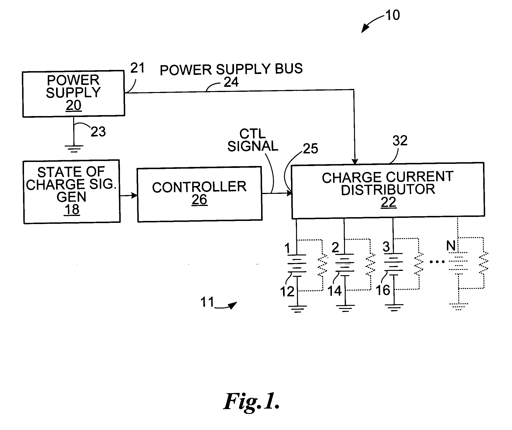
[0032] An apparatus for charging the batteries 12, 14, and 16 in the system, according to the invention is shown generally at 10. Generally, the apparatus 10 includes a state of charge signal generator 18 operable to produce state of charge signals indicative of the states of charge of each battery 12, 14, and 16 in the system 11. The apparatus 10 further includes a power supply 20 operable to produce a charging current and further includes a current distributor 22. Desirably the power supply may be controllable in that its voltage and current may be controlled. The power supply may be of the constant voltage, or constant current types.
[0033] The power supply 20 has positive and negative poles 21 and 23. The positive pole 21 is connected to the current distributor 22 by a power supply bus 24 and the current distributor is operable to selectively connect each battery 12, 14 and 16 in the battery system 11 to the power supply bus 24, in response to a control signal. The apparatus 10 f...
second embodiment
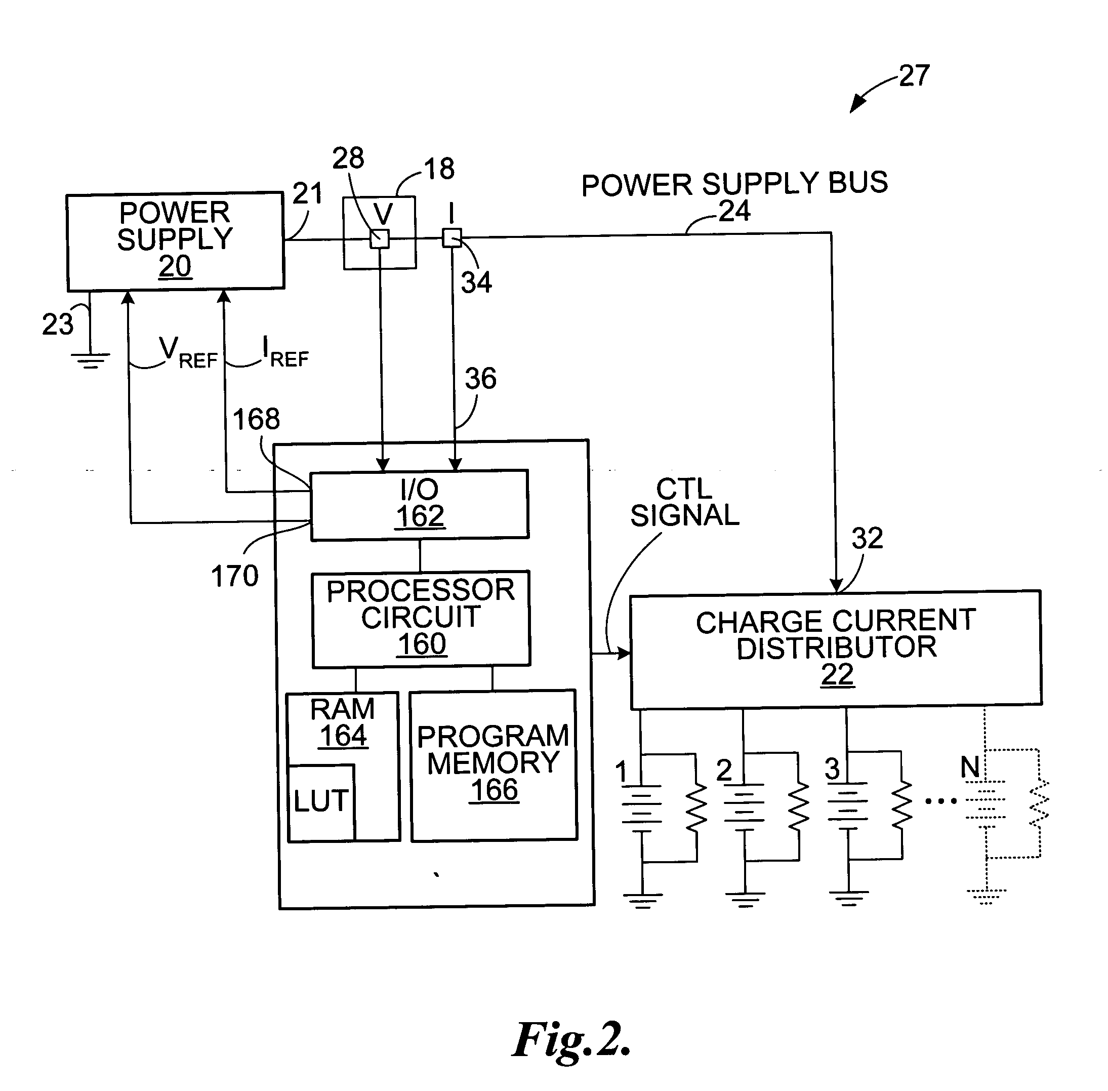
[0034] The state of charge signal generator 18 may include any device that produces a signal indicative of the state of charge of a battery 12, 14 and 16 in the battery system 11. Referring to FIG. 2, the invention is shown at 27 in which the state of charge signal generator 18 includes a voltage sensor 28 in communication with the power supply bus 24 to measure voltage on the power supply bus 24 when the current distributor 22 connects the power supply bus 24 to the most discharged battery. Alternatively separate voltage sensors (not shown) may be used on each charging port.
[0035] The apparatus 10 may include a current signal sensor 34 operable to sense current on the power supply bus 24 and operable to produce a current signal for reception at an input 36 of the controller 26.
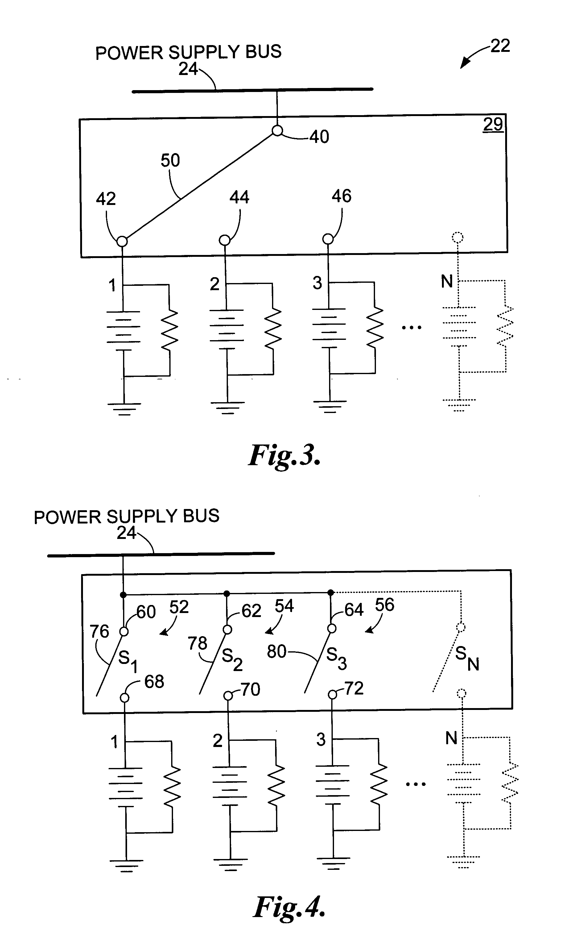
[0036] Referring to FIG. 3, the charge current distributor 22 may include a switching circuit 29 implemented as a single pole multi-throw switch having a common contact 40 connected to the power supply bus 2...
PUM
 Abstract
Description
Claims
Application Information
 - R&D
- Intellectual Property
- Life Sciences
- Materials
- Tech Scout
- Unparalleled Data Quality
- Higher Quality Content
- 60% Fewer Hallucinations
Browse by: Latest US Patents, China's latest patents, Technical Efficacy Thesaurus, Application Domain, Technology Topic, Popular Technical Reports.
© 2025 PatSnap. All rights reserved.Legal|Privacy policy|Modern Slavery Act Transparency Statement|Sitemap|About US| Contact US: help@patsnap.com


